You've probably seen various holiday or birthday cards that play a little jingle via beeps when they are opened. Last few years have brought new ones that play actual sampled music for a dozen seconds or so. I decided, for this new year's celebration, to make a card that, when opened, will play a complete song in full fidelity. And the song it should play should be selected randomly each time of many. The project would be housed in a normal CD jewel case. The project was further complicated by the fact that it is impossible to predict shipping times during the holidays. Thus the task was to do all this, using nothing but whatever materials and components that I already had at home. I managed to do this successfully, and the project worked well. It is not the best designed or the most efficient, but it does work.
The first task was actual music playing. This is of course nothing new. I've done projects that play music using 8-bit microcontrollers before, as have many others. In this case the only microcontroller I had access to was an attiny85. This, initially, seemed like it would be enough, but actualy ended up being a limiting factor later on. The code is simple, as expected. One timer is clocked from the 64MHz PLL to produce a high-frequency PWM signal that we'll use as analog output. Another timer is used to create the 32KHz sample clock. On sample interrupt, we take the next sample form the circular buffer and put in into the PWM duty cycle register. All the while, the main code is reading the file from the SD card, pausing only when the circular buffer is full. Thus music playback is realized.
Storage is provided by a microSD card. I used my SD driver from one of my other projects. The uFAT library was also used for basic read-only FAT16 access. The code enumerates all files whose extension is WAV and then randomly pickes one to play. It then collects the list of the card sectors that store that file and saves them in an array (up to 8 fragments per file are supported). File header is ignored, as are bytes in the last cluster that are not file bytes. This is not a real issue, however, since at 32KHz, the file header is merely 2.25ms long, and each sector of garbage at the end is merely 16ms. Neither is really perceptable.
Volume was not an immediate concern, but after the first prototype worked, it became one very quickly. The ATTiny can source/sink only about 20mA on a GPIO pin. And since it was running at 3.0V (at the time the power source was a set of two AAA batteries in series), the most power we could produce was 60mW. Not too loud at all. At this point, it was decided to add an amplifier. Luckily, the signal is digital, and so amplifying it is simple. I decided to use a full-bridge configuration of four MOSFETS with low on-resistance to get the +/-3V voltage swing to the speaker, with only 100-150 milli-ohm of series resistance. This means that now the power delivered to the 8-ohm speaker could be as high as 5.8W. Much louder. However, a problem lurked. To drive a full bridge one needs two complimentary signals, ideally with some dead time, due to MOSFETS having a non-zero switching time. I had no extra GPIO pins to use, so even ignoring the dead time, I had no complimentary drive signal. I decided to throw efficiency to the wind, and just make an inverter using an extra FET. This actually adds more delay, so in fact the two halves of the bridge will now stay both on for longer, wasting more power yet. Due to the contrainsts of the projects not allowing me to get a microcontroler with more pins, this was deemed acceptable. This was assembled on a small piece of protoboard, using some SMT parts I had around. It also worked wonderfuly! The speaker was now loud enough to be heard in the next room, and with no distortion too!

The two AAA batteries soon ran out, shortly after the addition of the somewhat-inefficient amplifier. This was not a concern since AAAs will not fit in a CD jewel case anyway. Given the power-bungry nature of the amplifier, I decided to use a Li-Po battery. I rummaged in the parts bin and found a 230mAh battery which was, at this point, probably only good for 180mAh or so, given its age. I also did find some SMT parts from previous projects, enough to make a rudimentary charger and to use as 3.3v regulator. This was assembled on another piece of protoboard and worked wonderfully. (Later, a "charge complete" LED was added by connecting an LED + resistor between the STAT and GND pins of the charger chip).
Turning on when the case is opened was to be the main feature of the card. I experimented with a few different methods of accomplishing this, but none fit into the physical space allowed. Those that did, did not work in the way I wanted. I wanted a clean break between the battery and the regulator, to increase the shelf-life. After some experimentation with various cardboard cutouts of levers and flexible strips of metal, I had an idea that would work. A flexible strip of metal, bent and soldered down, such that it wants to stand up from the board at an angle of about 30 degrees. Above it a shape of an inverted "U", soldered down too. This way, with no external force attached, the upward force from the bottom piece forces its middle to touch the U-shaped top piece and a contact is made. When the case is closed, it presses down onto the very tip of the bottom piece (its tallest point from the board) and forces it down, breaking its connection to the U-shaped top piece, whose height is such that the closing case does not touch it. This worked very well, and was chosen as the final solution to this problem.
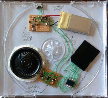
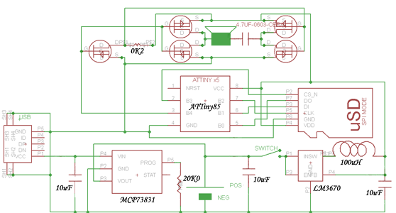
The final schematic of the resulting device can be seen here, as well as the picture of how it all looks together and a short video. I chose to use the back of the CD inset to label the components, thus making it somewhat interesting to look at. The power draw at 4.0V was measured to be about 320mA when playing a song. For the playback volume achieved, this was deemed acceptable, especially given that the card is rechargeable.
The code is available in the archive => [HERE] <= and is free for non-commercial use. It will pick a random song to play at each startup, assuming the card has in its root directory a set of .WAV files at 32KHz sampling rate and with 8-bit samples. After playing it will go to low power mode. On error a set of beeps will be produced, with each number of beeps indicating a different error. The random number generator is a simple linear congruential generator using the multiplicand 1664525, addend 1013904223, modulus 4294967296, and returning 16 bits each call. The seed is saved in EEPROM across runs.
Future improvements include actually laying out a board with a slightly different micro (more pins to allow for a better full bridge driver) to have a much more clean and efficent design. Suggestions are, of course, welcome in email or comment form. But, as it stands, the card fulfilled its purpose and played music of high quality at a significant volume, a random song each time.
