Remote Control mood light[/jar]
(updated Jun 14, 2011, 23:20 PDT - new firmware [v4])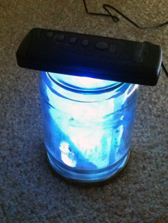
I wanted to play around with something IR remote-controlled, so I decided to make a remote-control mood light. There were two parts to the project: making the remote and making the light. For the remote, I tore down a remote control for a floor fan, removing all its insides, and replacing it with mine. I used a PIC12F1840 micro for the remote, mostly since I have a lot of these lying around. For the receiver, I used the same microcontroller. The enclosure for the mood light? a glass jar with some paper to diffuse the light (I am not too much into making enclosures). There were some interesting issues along the way, but now the project pretty much works. It has 4 high-brightness LEDs in it: White, Red, Green, and Blue.
Features? Currently the device has 2 modes, switchable using the "Mode" button. "On/Off" turns the device on and off, as expected. Settings are backed-up in EEPROM, so after any power loss, device comes back to the same mode and settings as it was in when it was last on. Fade mode fades between colors randomly, with adjustable speed and brightness. Adjustment is made using the "up"/"down" buttons. What is adjusted is selected using the "O" button. Increasingly bright white blinks after pressing the "O" button mean you're in brightness adjustment mode. White, Red, Green, Blue flashes after pressing the "O" button mean you're adjusting speed. Solid mode is a solid color, each of whose WRGB components is adjustable up/down using the "up"/"down" buttons. Current component is selected using the "O" button - when pressed, it flashes just that color for half a second to indicate what you're adjusting. Selected color is saved when you switch modes, and restored when you re-enter solid mode. When in off mode, you can anter diagnostic mode by entering on the remote: "Up Down Up Down O O". This shows some values using LEDs. Each value is preceded by a color to indicate the meaning. Then decimal digits of the value are sent, one at a time, using dimwhite blinks. The end of each digit is signified by a bright white blink. So to send 102 we'd see a dim white blink, a bright white blink, another bright white blink, two dim white blinks and a bright blink. For now only two vales are shown. Software version (color code green) and remote battery voltage (color code blue). The code is very modular, so adding new modes is dead easy.
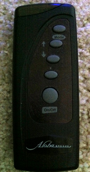
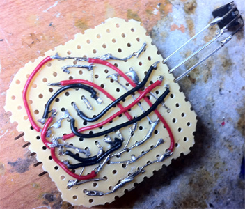
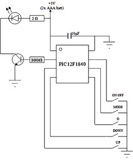
The remote has 5 buttons, with black labels on grey background. I used a sharpie to color the background black, hiding the labels, except "on-off" and "mode." Outlines of arrows were left grey next to two buttons and a circle next to third. So now the buttons are "Mode", "Up", "Down", "O", "On/Off". Internally, the PIC reads the buttons by connecting them to pins RA0 - RA4, with internal pullups enabled and the other end of buttons grounded. This is where I hit the first snag. I was expecting to use Interrupt-On-Change to wake the PIC from low-power sleep when a button is pressed. No matter what I did, this feature would not work. I had used it on previous models of PIC devices successfully, and I've been through the doc over and over, with no results. I am now reasonably convinced that this must either be a mistake in the docs, or a silicon problem. Now this was a major problem. No low power sleep means no way to not run through another set of batteries every week. After some thoughts, I decided to measure the power consumption of the PIC while running on its LFINTOSC oscillator at 31KHz. It was less than 0.01mA. I guess this is low power enough. So now whenever I need to wait for button presses, I switch to LFINTOSC, and repeatedly read the port pins and look for changes. I would love to have a working sleep mode, but sadly that appears impossible with this chip. The chip switches to 4MHz HFINTOSC-generated speed when sending a signal, and then back to low power mode when it is done with that.
The physical layer of the communication on the remote side is a single 940nm IR LED with a 38.6 KHz carrier frequency (generated by the CCP/PWM module). Data is sent in 8-bit bytes, MSB first. Each bit is a sequence of 0.5ms of modulated light, followed by 1 or 1.5 ms of darkness. 1.5ms means bit is 1, 1 ms means bit is 0. This means that the very last bit of the packet is impossible to discern, since the pause goes on forever. This is OK. The data packets are structures as follows: 1 byte preamble (0xFF), 1 byte header (0x05), 11 bytes data, 1 byte CRC, 1 byte trailer (0xFF), for a total sent packet size of 15 bytes. The last bit, as previously stated, is not readable, so trailer is actually ignored. Why, you may ask, do I have 11(!) bytes of data if I only have 5 buttons? I wanted to provide more than just a button press for future use, so data packet is structured as follows: numPresses: 32-bit, number of button presses done on remote in its lifetime; pressesSinceBattChange: 32-bit, number of presses since last loss of power; battVoltage: 16-bit, battery voltage in units of 1/100 volt; button: 8-bit, currently pressed button. Currently I am using the button and voltage fields, but I plan to use others, eventually, for something. The CRC is calculated over the packet date itself, and not the preamble or header.
The battery voltage is measured in a rather interesting way. As you can see on the schematic, there is no resistor divider network, and no analog pins. Instead, I enable the internal voltage reference to output 1.024V, and use that as the ADC input, while using Vdd as Vref for the ADC. This yields a result, which can, with some math, be used to calculate the voltage. The ADC is sampled 16 times, in hopes of gaining some extra precision. Unlike the usual method of measuring voltage, this method has varying degrees of accuracy, ranging from 0.02V on the low side to 0.1V on the high side. On the other hand - no need for extra external components and no pin waste on analog pins. I also tried to use the PIC's internal temperature sensor, but found it wildly inacurate, so I gave up on it.
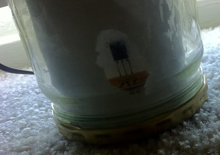
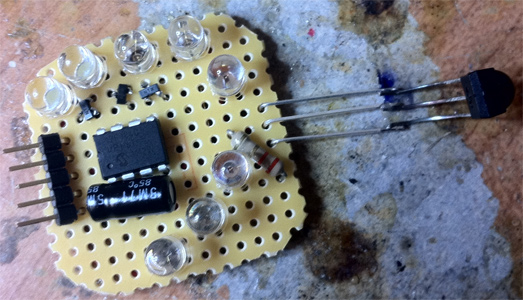
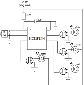
The receiver (mood light itself) is housed in a glass jar, with paper inside to diffuse the light. Yes, I know it looks quite odd. On the left you can see a close-up of the IR receiver. It is a standard generic radioshack 38KHz IR receiver. Its output idles high, and goes low when it detects 38 KHz-modulated IR light. The brains of the receiver is, as stated previously, a PIC12F1840. Here it runs at 32MHz though. It does everything the receiver needs to do. Timer0 is used with a 1:2 a prescaler, its overflow interrupt is used as a counter for the 4 PWM channels for the 4 LEDs, yielding PWM frequency of 61Hz and 8-bit resolution for each channel. Timer1 runs with a 1:8 prescaler, yielding a 1MHz tick, which is used together with the CCP module to capture IR receiver's output timing precisely. Any pause over 1.1ms is considered a 1, else it's a zero. Timer2 is used at 1:64 prescaler, yielding a 125KHz frequency, its overflow is postscaled by 1:2, resulting in an overflow interrupt once every 4 ms or so. We use this as IR timeout. After every received bit, we reset Timer2 to 0, if it ever overflows, we have a timeout since 4 ms passed and the longest a bit can be is 2ms. IR receiver is connected to RA5. RA0, RA1, RA2, and RA4 are used as outputs, connected to gate of N-channel MOSFETs, which drive the LEDs. RA3 is unused in this design.
The receiver code is pretty modularized, making it easy to add new modes of operation. A table of function pointers is used, where each mode provides an array of them in this order:
- init - called when mode is just entered. Should load any data it needs from EEPROM and initialize LEDs to wanted state
- destroy - called when mode is exited. Should save any persistent data to EEPROM
- btn_up - called when user presses the "UP" button
- btn_down - called when user presses the "DOWN" button
- btn_o - called when user presses the "O" button
- data_init - called first time device boots, or if EEPROM appears to be corrupt. Allows module to init its EEPROM data to a known state
- run - called at most once every 64ms - allows module to update LEDs, if it so wishes
The code (Hi-TECH C is used to compile it), as well as the ASM files and hex files are downloadable here: [DOWNLOAD]. Feedback is always welcome in [EMAIL] form.
EXTRA phtos of the second build + video: