Remote-Control Light Dimmer
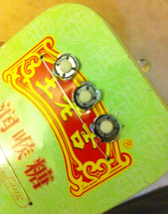
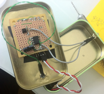
The lamp in my bedroom is a very cheap lamp from Wal-Mart. It stands in one corner of my room, opposite of the door. This is where the problem is: If it is dark, I have to walk across the room, not trip on anything, find the small knob to twist to turn on the lamp, walk back towards whatever I need to do in the room. That is a whole lot of unnecessary walking. As can be imagined, this annoyed me. I decided to make a remote-control for the lamp. And since I was making a remote control, I decided that I might as well make it a dimmer - something I've wanted from this lamp for a while. I lacked any enclosures, so I used a tin can from what I can only assume were Chinese Altoids.

The IR protocol is very simple. At the physical layer I stole it from a previous project of mine. IR 940nm LED is used. The carrier frequency is 34KHz. A 1-bit is sent with 0.5 ms of modulated carrier and 1.5 ms of darkness. A 0-bit is sent with 0.5 ms of modulated carrier and 0.5 ms of darkness. The packet begins with a preamble byte of 0xFF. Then comes a header of 0x06. Then comes the device ID - a 32-bit identifier of the device. For this project, I used a device ID of {'A' 'B', 'L', '1'}. Then comes the button code. 2 bytes are used, big-endian. This project uses just three button codes: 0 for "power on/off", 1 for "brightness up," and 2 for "brightness down." Then comes a checksum. It is used to make sure that the packet is received successfully and error-free. Then comes the trailer byte of 0xFF. This protocol allows for over 4 billion device types and more than 65 thousand buttons for each.
The transmitter uses a rather low-end microcontroller. It uses a PIC12F509 I had lying around. This microcontroller runs at 4MHz and has very few resources and almost no peripherals. Almost all of the chip's abilities are used in the transmitter. Normally when the remote is not being used the PIC is in low power sleep. GPIO-change notification-reset is used to wake the PIC when a button is pressed. PIC's own internal pullups are used to avoid needing pullups on the buttons. GPIOs 0, 1, and 3 are the button GPIOs. GPIO 2 goes to a transistor that drives the IR LED. GPIO 5 connects to a blue LED on the remote's face. watchdog timer on the PIC is setup to time out after about 800ms. Why? When the remote is off, it waks up every 800ms, blinks the blue LED, and goes back to sleep. Why? Have you ever tried to find a remote in a dark room? Any luck? This may seem like a big power draw, but: (1) LED is driven with a PWM at 1/100 duty cycle and (2) it is only on for 1ms out of every 800ms. This means that effectively it is adding no power draw to the device. The measured average power consumption of the whole remote while idle is about 11 microamperes. The source code is rather direct and to the point. The remote also features auto-repeat for buttons. The initial delay between a button press and the first auto-repeat is 700ms. After that the code is resent every 50ms. This allows you to raise or lower the brightness in one smooth motion. It also allows you to annoy people by holding down the power button and watching the lamp flicker on and off.
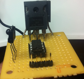
The reciever is based on the PIC12F617 running at 8MHz using the internal RC oscillator. The device's Capture / Compare / PWM module is used in compare mode to time the IR receiver's output pin's high time. The receiver output is normally high and goes low when it detects 38KHz-modulated IR light. Capture mode captures Timer1 values, thus Timer1 is enabled. It is set to run at 1MHz, so that our delays for 0 and 1 are about 500 and 1500 in terms of Timer1 ticks, respectively. Since we time the "high" time, and a lack of an IR signal is high, we might never end our wait for the next bit to start. Timer2 is used to create a timeout. Every time a new bit starts, we reset Timer2 to zero. It is programmed to interrupt us after about 4ms. Since no valid codes have 4ms of dark time, if we ever get a Timer2 interrupt, we know that the code is over. Since the PIC has only one Capture/Compare/PWM peripheral, we need to PWM the Lamp in software, which we do with a frequency of about 977Hz. Timer0 is used for this, with a 1:8 prescaler. I mentioned PWM at 977Hz. This means that we cannot use a relay to control the load. Not only would that be extremely loud, it would wear the relay out very quickly. Instead we use a power N-Channel MOSFET IRF250. This begs to question: how do we control AC with a MOSFET? We rectify it first. If you place a full-wave rectifier in series with an AC load, you can control the rectified result instead. The IR receiver is the standard 3-pin reciever you can buy in any RadioShack. Please make sure that the supply you use for 5V is transformer-based since a switch-mode supply could cause a very unpleasant fire.
This approach is is easily extensible to control any number of different things around your house, just use different "device ID" numbers. The code can be compiled with Hi-Tech C compiler for PIC and can be had here: [LINK]. The video on the right shows a small demonstration of the project in action. Commente/grievances/suggestions/complaints/ideas can be sent to [EMAIL].
