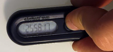
Most of us have seen theses OTP/eToken devices around. They are cheap, plentiful, easily available on eBay, and actually somewhat useful. The theory of operation for these is relatively simple and well-understood. The two main varieties are time-based tokens and event-based tokens. Time-based tokens are usually the ones that always have the display on and generate a new passcode every minute or so. Event-based ones are the kind that generate a new passcode when the user presses a button, and after that go back to sleep. These are the ones that usually do not have their screen on at all times. The actual codes are usually generated by hashing a secret key and a counter together. The particular token I was playing with (Aladdin PASS) uses SHA1 and is event-based.
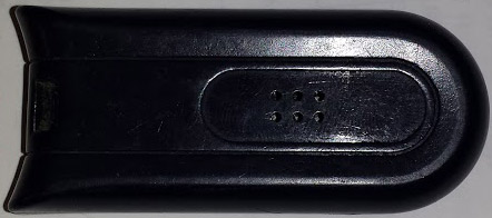
Since the token I had was not of any use to me, I decided to see what else I could do with it. Logically, they must be somehow provisioned, so I looked for that way. Lo and behold, the back side hid six holes in a 3x2 arrangement under a long-since-worn-through sticker. I guesses those holes were made for pins to go through, to contact the board inside. Sadly, since there were no labels, I had no clue as to whether they were indeed meant to contact something inside, and, if so, what and how. It was time to break the plastic case open and peek inside.
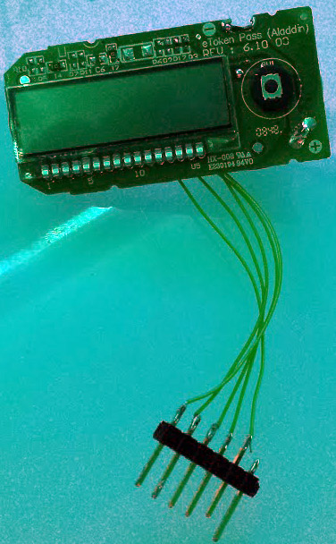
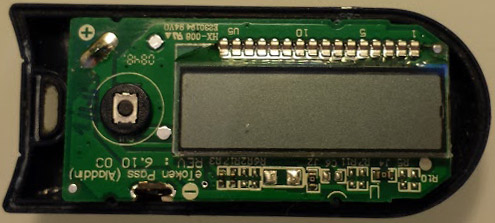
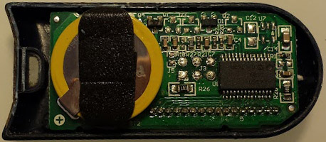
A few seconds of prying was all that it took to open the device. Here are the photos of the very simple board inside. The one and only IC is marked as HA4450. Searching the web for that model number brought up only fake chinese sites claiming to be able to sell me thousands of these for cents. None of them told me what that chip was. It did, however, have a Microchip logo. But, they had no such model listed on theit site. I decided to try and guess what it was. I used their parametric search tool to list all 28-pin(as this chip was) 8-bit(any more bits would be overkill) microcontrollers with LCD controllers(doing LCD by hand is a huge pain) with EEPROM (they need to store the persistent state somewhere, I figured), and available in SOIC packages. There were 6 results; 4 of them were PIC16F1xxx, which I know are relatively new. These tokens, however, I know have existed forever. So I guessed the PIC16F1xxx was not what I was looking for. Left were only two options. PIC16F913 and PIC16F916. This was all, of course, just a guess. Since those two differ only in amount of flash and RAM, for my purposes they are the same. Next step, if I were to assume that this was a PIC16F913/916, was to verify the wiring made sense. It did. All pins that you'd expect to be ground were. The power pin was powered and the 6 pads under those holes corresponded to the Microchip ICSP pins of the controller. The pins on the board were (in order): MCLR, VDD, GND, ICSPDAT, NC, ICSPCLK.
It was time to check my guess. I wired up a 5x1 header and plugged it into my PICKit2. What do you know? The PICKit2 application recognized the chip as PIC16F913. Cool! The device was code-protected and data-protected. Well then, no backing it up! It accepted an erase properly, and a test program-and-erase cycle went well too. Whether I liked it or not, I now had a blank slate to play with. The wiring was still a mystery. The LCD display had 16 wires going to it, and it was able to, at least, display 6 7-segment characters, making for at least 42 segments total. Given the number of wires and segments, we can safely conclude that it must be at least a 4x MUX. Given that the PIC16F913 does not support any MUX over 4x, we must conclude it is indeed a 4x12 mux, allowing for a maximum of 48 addressable segments. Checking the wiring did, indeed, show the LCD connected as a 4x12 to COM1..COM3 and SEG0..SEG11. If we number the on-screen characters and use the standard 7-segment segment names, the memory layout was:
| LCDDAT0,LCDDAT1 | a0 | a1 | a2 | a3 | a4 | a5 | ||||||
| LCDDAT3,LCDDAT4 | f0 | b0 | f1 | b1 | f2 | b2 | f3 | b3 | f4 | b4 | f5 | b5 |
| LCDDAT6,LCDDAT7 | g0 | c0 | g1 | c1 | g2 | c2 | g3 | c3 | g4 | c4 | g5 | c5 |
| LCDDAT9,LCDDAT10 | e0 | d0 | e1 | d1 | e2 | d2 | e3 | d3 | e4 | d4 | e5 | d5 |
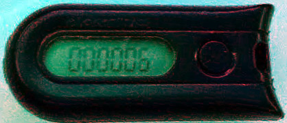
I did not need a security token, but I could use a keychain-sized timer. I decided to make that. The code is simplicity itself. My simple LCD driver allows one to set any segment on or off, or to draw a hexchar (0..9a..f) at any location as well as power up and down the LCD. The code starts in start-wait state wherein it blinks all zeroes on display and waits for a button press to start the timer, or a 10-second timeout. If the timeout happens, the device goes to sleep, else the timer starts. It runs until the button is pressed again. Then the timer stops and enters the sleep-wait mode. Here it blinks the last recorded time, and waits for a timeout (20s) or a button press. After either of those the device goes to sleep. I used TMR2 to keep track of time (interrupting at 25Hz) and TMR0 for button debouncing (overflowing at about 8Hz). I ran the CPU at 1MHz. In theory, lower speeds are possible, but then the LCD starts flickering if clocked from the internal clock, since it has a hardwired 1:8192 clock divider. Clocking it off the LFINTOSC does fix this, but then we're forcing LFINTOSC to be powered up, wasting more power yet. You may ask about the accuracy of my "timer". Microchip specs the internal oscillator to be +/- 2%, which was more than good enough for my purposes. While asleep the device now consumes about 0.015mA and while running - 0.22mA. That is to say that the battery will last forever.
The chip has space for 4096 instructions, 256 bytes or RAM, and 256 bytes of EEPROM - you can do more exciting things with it if you so wish (like, for example, implementing your own custom OTP algorithm). My code (under the apaches 2 licence) can be downloaded [here]. Included in the archive is the source code for my timer implementation and the LCD driver, as well as a pre-compiled HEX file, in case you really want a timer like mine, and do not wish to muck about with compiling it yourself. As a sidenote: I never did figure out what the part number HA4450 meant. Perhaps it has some hardware crypto assitance, or maybe it is just a custom part number microchip made for Aladdin (pre-programmed with their code possibly). Well, in any case, this should help you get started with hacking these very very easily-available devices. Enjoy.
