A smart 3LS363A
Smart 3LS363A
3LS363A
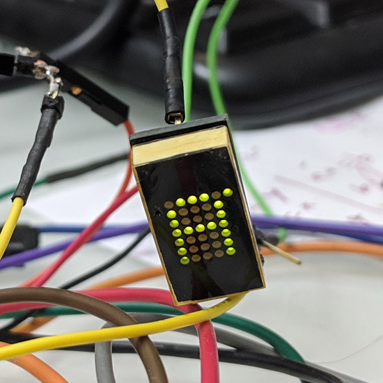
These displays were used back in the USSR to display various things in military devices, calculators, and terminals. They are 5x7, with an extra dot for decimal points. They contain no smarts of any sort, just 36 green LEDs. I wanted to make a project with a lot of these. Driving them all at once from a single micro would be very annoying. Plus, I did not know how many I would like to use in my project. Clearly the solution to to find a better way to control them.

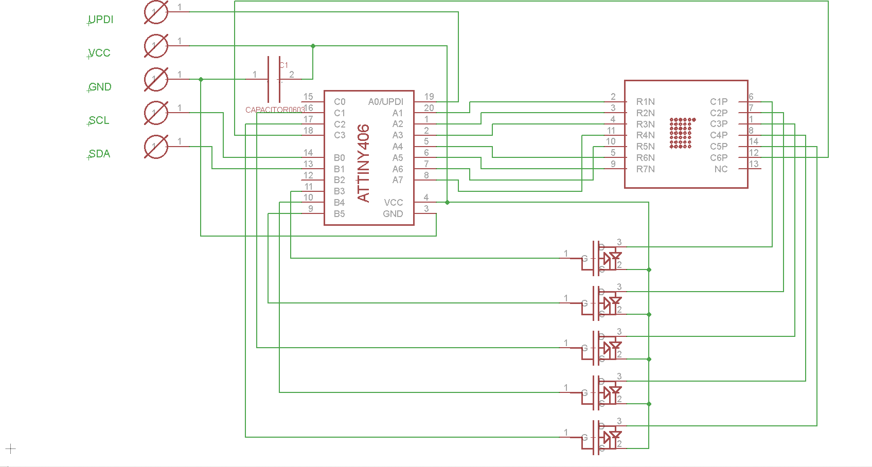
I decided to design a small board to fit perfectly behind the display and allow it to be controlled over i2c. The idea was to allow many of these displays to be hooked up to the same four wires (GND, Vcc, SDA, SCL) and control them all. There were, of course intricacies, like address assignment, and avoiding tearing, but they were solved. For the main MCU I chose the ATTiny406, mostly for its size, number of GPIOs, and i2c slave hardware.
The Code
The code I wrote ended up fulfilling all the requirements I had, and then some. To start with, the firmware is updateable, and updates can be streamed to the device while it is still operating, the next reset it will boot into the new version. The built-in character table covers the entirety of printable ASCII range, and you can also upload a raw bitmap if you want to draw your own images. There are persistent flags that allow horizontal or vertical image flipping, for various mount configurations, the i2c address is assignable at runtime, and there is even a way to discover all devices on the bus with the same address.
Each device will always answer to i2c address zero. Each device may also be assigned another i2c address. Why both? For instant updates. Imagine that there are thirty of these all on the same bus. If one were to send each one a new character to show, they'd not update at the same time. So how does this get resolved? Double buffering. Send each unit a new character to show. The unit will remember it, but not show it. Then, to address zero, send the "Flip" command and they all flip to this saved new character instantly. This also works for sending raw bitmap data.
Assigning unique addresses to identical devices is potentially complicated. The code here resolves that easily. Each device has a unique 16-byte ID based on the unique ID of each ATTiny406. I2C collision detection is used here. A command "all send UID" can be issued, and only devices with no assigned i2c address will reply with their UID. The i2c collision resolution will take place and the device with the lowest (numerically) UID will be the only one that gets to complete sending the reply. After this, "Assign i2c addr by UID" command can be sent to address zero, and only the device with the stated UID will accept that new address. This procedure can now be repeated, since this device will no longer reply to "all send UID" command sent to address zero. There is, of course a way to get its UID anyways, just send that command to its actual address. Of course the device can be assigned the address zero to return it to original state, if desired. The address is stored in EEPROM and persists across power cycles.
Firmware updates are sent over i2c as well, and can in fact even be sent to address zero (to update all devices at once). The updates are sent in 64-byte chunks, and the chunks may be sent in any order, except that the very first chunk (address offset zero) must be sent last since the bootloader uses its presence to decide if the update should be considered for application. If the update upload is interrupted, it can be resumed at a later time. If the device is interrupted while an update is being applied, the application of th eupdate will continue next boot, so the device cannot be bricked in any way. The total size of the update is 0x700 bytes. This is due to 256 bytes being used for the bootloader, and the remaining flash being split between main code and update storage. Currently there are only a few bytes free in the binary, but removing character generation could provide a lot of spacing (and bitmaps can be uploaded by the host just as easily).
The Hardware
To save board space, I decided to drive the display a column at a time. There are six columns, and five FETs. What gives? Well, one column only has one LED in to (the decimal point) so it can be driven with a gpio directly. Others use P-FETs to provide the column power. Rows are all connected to GPIOs directly. Since the duty cycle is low, and AVR GPIOs cannot sink a lot of current, current limiting resistors are not used. The microcontroller lives under the display on top of the board, together with the decoupling cap. The five FETs live below. There is a single test point/hole on top of the board for UPDI (to program the AVR the first time) and four on the bottom at 0.1 inch spacing for interfacing with the display: SDA, SCL, GND, Vcc.
Comms Protocol (over normal i2c as we all know and love it)
CMD_RESET(0x00) simply resets the display. Can be sent to a specific address or to the broadcast address zero. No reply is expected. If a complete firmware update had been uploaded previously, it will be applied on boot.
CMD_FLIP(0x01) Flip the backbuffer to frontbuffer. That is: display onscreen whatever was last sent as data (character or bitmap). It is at this point that horizontal and vertical flip is applied. Can be sent to a specific address or to the broadcast address zero.
CMD_SET_ADDR(0x02) Set i2c address. Followed by one byte to be used as the new i2c address. It should be in the range 0x01..0x7f. Can be sent to a specific address or to the broadcast address zero.
CMD_SET_ADDR_UID(0x03) Set i2c address for the device whose UID is provided. Useful after device discovery. Followed by 16 bytes of device UID, and then one byte to be used as the new i2c address. It should be in the range 0x01..0x7f. Can be sent to a specific address or to the broadcast address zero.
CMD_GET_UID(0x04) Get device UID. Collisions are expected if multiple devices are present. Lowest UID wins. Can be sent to a specific address or to the broadcast address zero. If a device has a non-zero i2c address assigned, and the command was sent to broadcast address (zero), the device will not respond. this is to allow device discovery to proceed. A device will always respond if this command is sent to its assigned non-zero address. If more than one device is assigned the same address (allowable), once again collisions are handled and the master will read the lowest UID.
CMD_DRAW_BMP(0x05) Followed by 6 bytes of data. Each byte represents a column. Lowest bit represents row 0, next bit is row 1, etc. Top bits are unused since the display only had 7 rows. Column 5 only has row 0 (decimal point). Can be sent to a specific address or to the broadcast address zero.
CMD_DRAW_CHAR(0x06) Display a char. Followed by a single ASCII char. Nothing is done if the requested char is not in printable range (0x20..0x83). Normally the printable range is 0x20..0x7F, but I added four more chars: arrows. 0x80 is UP_ARROW, 0x81 is DOWN_ARROW, 0x82 is RIGHT_ARROW, 0x83 is LEFT_ARROW. Can be sent to a specific address or to the broadcast address zero.
CMD_GET_VER(0x07) Get current device hardware and firmware version. After sending this, perform a restart procedure and a read. Read two bytes. First is hardware version (currently 1) Second is firmware version (currently 2). Can be sent to a specific address or to the broadcast address zero.
CMD_FW_UPDATE(0x08) Send a firmware update chunk. Each chunk contains 64 bytes of update data preceded by 2 bytes of address. All updates begin at address 0x8800. Update chunks can be sent in any order, except that the very first chunk (the one at 0x8800) should be sent last. Can be sent to a specific address or to the broadcast address zero.
CMD_SET_FLAGS(0x09) Set the flags byte. It persists in EEPROM. Currently only two bits of the flag byte are defined. Lowest bit, if set, causes the image to be flipped horizontally. Next bit does the same for vertical flipping. The flipping applies to both uploaded bitmaps and character images rendered by CMD_DRAW_CHAR. If a bitmap is uploaded, the decimal point is NOT ever flipped (since there is only one such LED). Can be sent to a specific address or to the broadcast address zero.
CMD_GET_FLAGS(0x0A) After sending this, perform a restart procedure and a read. Read one byte - it will be the current flags value. Flags are described above Can be sent to a specific address or to the broadcast address zero.
How do I make one?
The makefile in the sources will produce both a hex file for initial flashing (including the bootloader) and the binary file for updating over i2c. The update protocol is easy. Send 64-bye chunks using the "UPDATE" command and precede each with a 16-bit little endian target address, starting with 0x8800. Then issue the "RESET" command. Easy.
Here you can download the schematics and board files (eagle 6 version), gerbers, sources, and binaries. Enjoy: => [LINK] <=
