Table of Contents
- Why?
- Parts selection
- What to emulate
- Let's emulate!
- Bring on the hardware!
- How it works
- Improving performance
- How to build and use one
- Version 2
- In conclusion
- Comments...
Why?

A long long time ago (in 2012) I ran Linux on an 8-bit AVR. It was kind of a cool record at the time. I do not think anyone has beaten it - nobody's managed to run Linux on a lower-end device than that 8-bit AVR. The main problem was that is was too slow to be practical. The effective speed was 10KHz, the boot time was 6 hours. Cool, but I doubt that any one of those people who built one of those devices based on my design ever waited for the device to boot more than once. It was time to improve it!
So what could I improve? A number of things. First, I wanted the new design to be speedy enough to boot in a few minutes and reply to commands in seconds. This would make using the device practical and not a test of patience. Second, I wanted it to be easy to assemble for anyone. This meant no components with tight spacing, no components with too many pins, and no components with contacts hidden underneath them. A part of this wish was also that someone could actually assemble one, meaning that I had to select components that are actually buyable in the middle of the current ongoing shortage of, well, everything. Additionally, I wanted the device to be easy to interface with. The original project required a USB-to-serial adapter. This would not do. And, finally, I wanted the whole thing to be cheap and compact enough to serve as my business card.
Parts selection

Some things were pretty easy to decide on. For storage, for example, microSD is perfect - easy to interface with, widely available, cheap. I picked a simple microSD slot that is easy to solder and easy to buy: Amphenol 1140084168.
Some choices were a litle harder, but not too much so. For example, I was surely not going to use DRAM again. It requires too many pins, necessitating more soldering than I would consider acceptable, given that I wanted this device to be easy to assemble. SRAM in megabyte sizes does not really exist. But there is a cool thing called PSRAM. It is basically DRAM, but in easy mode. It itself takes care of all the refreshing and externally acts just like SRAM. Ok, cool, but still that would usually be a lot of pins. Right? Enter "AP Memory" and "ISSI". They make QSPI PSRAM chips in nice SOIC-8 packages. AP Memory has models with 2MB and 8MB of RAM per chip, ISSI has them in 1MB, 2MB, and 4MB sizes. I decided to use these. They are available and my code supports them all!
There were some miscellaneous choices, like which regulator to use. I chose MIC5317-3.3YM5TR due to having worked with it before and it being available in my "random chips" box. It is also easily available to buy.
The USB connector was also a fun choice. I settled on: none. With the proper PCB thickness, one can lay out the board edge to fit into the end of a USB-C cable. I've seen this done before for micro-USB and figured it could be done for USB-C as well. At the end, though, I did not even need to do it, since someone else already saved me the 30 minutes it would have taken. I just had to remember that the board thickness needs to be 0.8mm for this to work.
The last choice was the hardest - which microcontroller to use. The criteria were: built-in USB, no more than 32 pins with at least 0.65mm spacing, no pin-less packages, actually available to buy, QSPI support, as fast as possible. I did not get my last two wishes. After much searching and filtering for "in stock", I was forced to settle for an ATSAMD21 series chip, specifically the ATSAMDA1E16. It is not fast (specced to 48MHz, I clock it at 90MHz), it has many bugs (especially in its DMA engine), but it can be bought, it is easy to solder, and it'll have to do... UPDATE: another chip is now supported too, see later in this article.
What to emulate
I could have just taken my old ARM emulator (uARM) and used that. But what's the fun there? I decided to pick a new target. The ideal emulation target will: (1) be a RISC chip so that I have to spend fewer cycles on decoding instructions, (2) have no condition codes (like MIPS) or only set them on demand (like ARM), so that I am not wasting time calculating them every virtual cycle, (3) be 32-bit since 16-bit machines are all funky and 64 bit is a pain to emulate, (4) be known, and (5) have a workable set of GNU tools and Linux userspaces available. This set of requirements actually only leaves a few candidates: PowerPC, ARM, MIPS. I've done ARM, and I had no desire to mess with an endian-switchable CPU, so MIPS it was! This gives rise to the internal name of the project: uMIPS.
A MIPS primer
MIPS is old - one of the original RISC designs. If you are a RISC-V fanboy(/girl/being), MIPS will look familiar - it is where 99.9994% of the initial RISC-V spec was copied from. The original MIPS was a 32-bit design, optimized for ease-of-designing-it. It has (and does not hide) a delay slot, has a lot of registers, including a hard-wired zero register, and does not use condition codes. The original design was R2000, back in 1986, followed soon by the improved R3000 in 1988. These were the last chips implementing the MIPS-I instruction set. MIPS-II was short lived and only included the R6000, which barely saw the light of day. The real successors were the MIPS-III R4000-series chips, released in 1991. These were 64-bit already in 1991! Clearly, the easiest target would be the R2000/R3000 chips with their simple MIPS-I instruction set.
MIPS-I is a rather simple instruction set. So much so that a complete emulator of just the instructions can be written in under 1000 lines of C code without any dirty tricks. The floating point unit is optional, so it can be skipped (for now). The MMU is weird. It is just a TLB that the software must fill manually. This may seem like a rather unusual choice, but in reality it is a clever one, if you're in 1986 and tring to minimize the number of transistors in your chip. Why have a hardware pagetable walker, when you can make the software do it? You may ask how it handles the situation where the code that would do the walking is itself not mapped? Well, a part of physical memory is always hard-mapped at a certain address, and all exception handlers live there. Even if this were not the case, since the software manages the TLB, it would not be hard to reserve an entry for this purpose. The hardware even has support for some "wired" entries that are meant to be permanent. More on all of this later.
What system?
MIPS R2000/R3000 is a processor. A processor does not a complete system make. What system to emulate? I searched around for a cool system and settled on DECstation2100 (or its big brother - DECstation3100). Why bother? It seemed like a simple system that Linux does support. Initially I was not planning to emulate the whole thing. Why? I had no plans to emulate the LANCE network adapter or the SII SCSI adapter. The last part might surprise you, since we will need a disk to use as our root fs. I did later add emulation of both of these parts, to make Ultrix happy.
Let's emulate!
The CPU
MIPS is a rather old instruction set, which shows in a few places. The main one is that it attempts to prevent signed overflow. The normal instructions used for addition and subtraction will cause an actual exception if they cause an overflow. This does not map to how CPUs are used today, so nobody cares, but I still had to emulate it. There are "unsigned" versions of the instructions for addition and subtraction that do not do this, which is what all modern compilers will emit on MIPS.
I wrote an emulator for the CPU in C first, to allow easy testing on my desktop, while the PCBs were being manufactured. It was not fast, nor meant to be, but it did allow for testing. You can see this emulator in cpu.c. Along the way here, I implemented some features of the R4000 CPU optionally. It turned out that to boot Linux compiled with modern compilers, this is necessary, as the compilers assume these instructions exist. Technically this is a bug. Realistically, I am likely the only person to ever notice. So, which features did I need to add? Likely branches (BxxL instructions), conditional traps (Tcc/TccI instructions), and atomics (LL/CC instructions).
Of course, C is not the language one uses when one wants to go fast. I wrote an emulator in assembly too, targetting ARMv6-M (for the Cortex-M0 MCU I chose). I later added a sprinking of enhancements for ARMv7-M (in case I ever upgrade the project to a fancier CPU). This was tested on a Cortex-M7 and worked well too. The assembly emulator core is contained in cpuAsm.S and the ARMv6-M specific parts are in cpuM0.inc
I mentioned delay slots earlier. What is a delay slot? Well, back in the day it was considered cool to expose your CPU's pipeline to the world. Just kiding, it was just a way to save some more transistors. Basically, the instruction after a jump will be executed even if the jump happens. This is called the delay slot. A naive way to avoid dealing with this is to place a NOP after each jump instruction. But with a good compiler, the delay slot can be put to a good use in almost all cases. Obviously one cannot place a jump instruction in the delay slot, since the CPU is already jumping somewhere. Doing this is illegal and undefined. An issue arises, however, if the instruction in the delay slot causes an exception of any sort. The CPU will record that the instruction was in the delay slot, and point the exception handler to the jump whose delay slot we're in. There is no way to return to this "in delay slot" state, so the exception handler is expected to take steps to somehow execute the delay-slot instruction and then complete the jump.
The FPU
The DECstation came with an FPU, so that floating point operations would be fast. Back then this was a separate chip, which was optional in a MIPS R2000/R3000 system. Linux, in fact, will more-or-less corectly emulate the FPU if it is not present, but this is slow. I used this mode initially, and even fixed a few bugs in Linux's emulation, but, in the end, I implemented an FPU emulator. This was necessary since it seems like a lot of MIPS binaries I could find all assume the FPU is available and use it freely. I never reimplemented the FPU emulator in assembly, instead calling out to the C FPU emulator when needed. I figure that squeezing a few cycles out of each instruction is meaningless when the actual FPU operation takes hundreds. The code for this is in fpu.c. I include Linux patches to remove FPU emulation support from the kernel. This saves some RAM. Later, I also added support for a "minimal" FPU - it supports the registers but no operations. This is allowed by the spec, since the FPU may refuse to execute any operation it is "not sure it can do perfectly correctly", so any compliant OS must implement a full FPU fallback anyways. Why? This saves 16K of code size in the binary, opening the possibility of running uMIPS on smaller devices yet.
The MMU
MMU basics
(this is a very oversimplified summary, feel free to skip if you know this, and do not complain to me that it is not perfectly accurate!)
Most CPUs access memory using virtual addresses (VA). The hardware works in terms of physical addresses (PA). Ability to map one to the other is the underpinning of memory safety in modern operating systems. The purpose of an MMU (Memory Management Unit) is to translate virtual addresses to physical addresses, to allow for this mapping. Normally this is done using a tree-like structure in RAM, called a pagetable. Most CPUs have a component whose job it is to walk that structure to resolve what physical address a given virtual address maps to. This component is a pagetable walker. In most cases the pagetable has 3 or 4 levels, which means that resolving a VA to a PA requires reading 3 or 4 words from main memory. Clearly you do not want to do 3 useless memory accesses for every useful one. So usually another component is included in an MMU - a TLB (Translation Lookaside Buffer). Basically you can think of a TLB as a cache of some of the current pagetable's contents. The idea is that before you go off doing those 3-4 memory reads into the pagetables, you can check and see if the TLB has a matching entry. If so, you can skip the pagetable walk.
Clearly, like any cache, the TLB needs to stay in sync with the things it caches (the current pagetables). So, if the OS changes the pagetables, it needs to flush the TLB, since it might have stale entries. Usually, TLBs expose very little interface to the CPU, so there isn't a way to go read all the entries and remove only the newly-invalid ones. Additionally, this would be slow, so this is not usually done. However, invalidating the entire TLB also has costs - it needs to be re-filled, at the cost of 3-4 memory accesses per entry. This could hurt performance. A solution commonly used is called an ASID.
What are the four main cases when pagetables might be modified? (1) Adding a new mapping over a virtual address that previously was not mapped to anything, (2) changing permissions on on existing mapping, (3) removing a mapping, and (4) entirely changing the memory map (for example to switch to a completely different process). In case 1, no TLB flush is necessary, since no stale TLB entry can exist. Cases 2 and 3 do indeed require flushing the TLB, but they aren't that common. Case 4 is quite common, though. It is done at every context switch. One might point out that since we're changing the entire memory map, the entire TLB would be invalid, and thus flushing it isn't a problem. This is wrong. Besides mapping userspace things, the MMU also maps various kernel structures, and there is no point penalizing them.
If we could somehow tag which entries in the TLB go with which process, and temporarily disable them when another process runs, we could avoid a lot of context-swich flushing and the performance costs imposed by it. It would also be cool if we could tag entires that belong to the kernel and are valid in every process. Well, this exact technology exists in many MMUs. The idea here is that each pagetable entry will have a bit marking it as "global" (valid in all memory maps) or not. There should also be a register in the CPU setting the current ASID (Address Space ID). When a TLB entry is populated from the pagetables, the current ASID is recorded in it. When a lookup in the TLB is done, only entries matching the current ASID or those marked "global" will match. Cool!
The MIPS MMU
The idea at the time was to save transistors. Which of the above could be cut? Well, cutting out the TLB guarantees terrible performance in all cases. But that pagetable walker, do we really need it? What if we make the sotware do it? We can add a little bit of assistance, like ability to manage the TLB efficiently, but skip on the pagetable walker hardware. This is what MIPS did. Here is the MIPS virtual address space:
So, as you can see, some VAs do not map via the MMU at all. This means that code living there is able to run no matter the state of the MMU. Linux and Ultrix, predictably, put the kernel in kseg0. The kernel does, however, need to be able to dynamically map things in as well. kseg2 is one gigabyte of address space that is mappable via the MMU that the kernel can use. Memory-mapped devices will usually be accessed via kseg1. The 2 gigabytes at the bottom of the address range(kuseg) are for userspace tasks.
What entry in a TLB should one replace when one needs to insert a new entry? An obvious answer might be "the one least recently used", but that would require tracking use, which costs transistors too. A simplification is "the one least recently added". This is easy, but it hides a fatal flaw. Imagine your TLB has N entries, and your workload sequentially uses N + 1 addresses, such that each would need a TLB entry. Now you'll always be replacing the entry you're about to need, guaranteeing that you NEVER hit the TLB and do a lot of pointless pagetable walks. How do we avoid this? The simplest method is replace a random entry. Sure, it might be the entry you're about to need, but for an N-entry TLB the chances are 1/N.
Generating random numbers is slow in software, so MIPS R2000/R3000 provide some help. The CPU has a register called, literally RANDOM which is supposed to be constantly incrementing, every cycle. Since the "when" of "when will you next need a new TLB entry" is not predictable, this is as good as random, and requires very few transistors. The idea is that whenever you need to replace a TLB entry, you use a special instruction TLBWR to write to a random entry. I did not tell you about ASIDs by accident either. The MIPS R3000 MMU implements a 6-bit ASID.
Emulating the MMU efficiently
Emulating the R3000 MMU is a bit of a pain. Since any entry can be in any location, the proper way to do a lookup is to check each one. Doing a 64-cycle loop for every memory access is a non-starter speed-wise, of course. I use a hashtable indexed by the virtual address to keep all the TLB entries in buckets for faster checking. Using 128 buckets virtually guarantees that most buckets have zero or one entry in them, permitting much faster lookups. Initially this was a simple table of pointers, but this used too much RAM, so now it is a table of indices.
Communication
The DECstation had a few ways to communicate with the outside world. It had a built-in network card, which I do not emulate. It was optional, and I haven't found a use for it yet. Maybe I will later - it does not look complex. It also had a SCSI controller which one could attach hard disks and other SCSI peripherals to. Emulating this would be a fun challenge, and I'll probably get to it later, but I did not do it now - it was not necessary - I wrote a paravirtualized disk driver for Linux using hypercalls, more on this later. There was also an optional framebuffer card one could install that added support for a monochrome or a color display. Emulating these would also not be too hard, but my business card lacks a display, so I did not do it either - plus I am not even sure that Linux can make a use of it.
The last method of communications that the DECstation had was DC7085 - a serial port controller that is basically a clone of a PDP11-era DZ-11. It supports four serial ports at a blistering 9,600bps speed (or any integer division thereof). Each serial port was allocated a purpose, and they were wired to different connectors indicating this purpose. #0 was for the keyboard, #1 for the mouse, #2 for modem, and #3 for printer. To the machine they are all the same, this was just the purpose DEC assigned to them. The stock PROM would use #3 as serial console instead if it did not detect a keyboard at #0, thus it is customary to use #3 as serial console for Linux on the DECstation. My PROM surrogate does not bother looking for or supporting external keyboard, and just defaults to serial console on #3. That being said, since it is cool to allow multiple login sessions, I also export #0 #2 as a second virtual serial port, so that you may login from two serial consoles at once, and do two things at once. How cool is that?
So, how do I export these serial ports? When you connect the card to a computer, it'll show up as a USB composite device comprised of two CDC-ACM virtual serial ports. One of them is port #3, another is port #0 #2 on the virtual DZ-11. How will you know which is which? #3 has the boot console printing and will have the initial sh prompt. If you do not see this, try the other one, computers do not always number them in the order I export them.
Hypercalls
In the real world the PROM had to probe the real hardware to detect what was present where. As my PROM is running in an emulator, there is no need for such mess. We can simply request things from the emulator in an agreed-upon way. That way is a hypercall - a special invalid instruction that, if encounted in supervisor mode, the emulator will treat as a request for some kind of service. The instruction I chose is 0x4f646776, which is in the COP3 (coprocessor 3) decode space that was not allocated to any real purpose in these chips. The calling convention is close to the normal C calling convention on MIPS: parameters are passed in $a0, $a1, $a2, and $a3, return values are in $v0 and $v1. The $at register gets the "hypercall number" - the specific service we're requesting.
A few hypercalls are implemented. #0 is used to get the memory map. The parameter is word index of the memory map to read. Word 0 is "how many bits the memory map bitmap contains", word 1 is "how many bytes of RAM each bit represents", words 2 and on are the bits of the map, up to the total specified in word 0. This can be used to build a memory map that the PROM can furnish to the running OS and allows me to have discontinuous RAM. Linux supports this and I tried it, but did not end up needing it. It is here in case I change my mind and need it again.
Hypercall #1 outputs a single byte to the debug console (which is the same as DZ-11 port 3). This is used by the PROM and mbrboot to output debug strings without needing to have a complete DZ-11 driver in there. Hypercall #5 will terminate emulation. This can be used on the PC version of the emulator to quit peacefully.
Hypercalls #2, #3, and #4 are used for SD card access. #2 will return card size in sectors, #3 will request a read of a given sector to a given physical RAM address and reply with a nonzero value if that worked. #4 will do the same for a card write.
Bring on the hardware!
The honeymoon period
The first revision of this board came up well initially, after I sorted out the mess that is ATSAMD21's clocking system. I appreciate flexibility as much as the next guy, but this thing is TOO flexible. It took a lot longer than I'd care to admit to get this thing running at a sane speed and to enable some peripherals. The docs were too sparse to be of much use, too. Atmel, what happened to you? You used to have the best docs!
The first revision of the board had two memory chips, each on their own SPI bus, an SD card on an SPI bus, and USB with the proper resistors. The USB was perfect. Unlike everyone and their grandmother (STMicro, I am glaring at you), Atmel did not license annoying Synopsis USB IP. They made their own. It is easy to use, elegant, and works well. Seriously, it just worked. In two days I got the hardware to work and wrote a USB device stack. I tip my hat to the team that worked on the USB controller. That being said, I have concerns. My main issue: USB descriptors aren't small. They are constant. I'd prefer to keep them in flash. I'd prefer to, but cannot. The USB unit uses a built-in DMA unit to read the data to send. This DMA unit CAN access flash, but if you have any flash wait states enabled, it sends garbage. I suspect that Atmel only tested it for reading from RAM, forgot that some memories have wait states, and did not account for that. Keeping all my descriptors in RAM is a colossal waste of RAM, which there is only 8KB of. Remember that tiped hat? I rescind it, Atmel. I had to work around the issue by sending the descriptors one piece at a time (rather than letting the hardware DMA it all automatically) just to save the valuable RAM.
Using the SPI units directly worked well enough, until I tried to speed them up. Past about 18MHz The received data was garbled (missing a bit or two, all the following bits shifted). No amount of searching found an issue in my code, and all sample code did more or less the same things. My bus analyzer showed no issues. What gives? THIS GIVES (archived)! I was beyond furious when I found this forum post. Here I was, trying to build a fast device, and my SPI bus was going to be limited to the speed of a tired snail calmly strolling through peanut butter! With some more testing I found that the SPI units will work fine to about 16MHz, which I'll have to live with.
The SPI units have no FIFOs, so code must manually feed them one byte at a time and read one byte at a time. This means that there is space between bytes on the bus as code wrangles bytes in and out of registers and memory. This is a waste of potential speed. The solution is DMA. Luckily this chip has DMA. Unluckily, it is fucked beyond belief, to a point where I am beginning to suspect that it was designed by a sleep-deprived stark raving lunatic.
How not to design a DMA unit
A normal garden-variety DMA unit has some minimal global configuration, and a few channels, each independent from the rest. Each channel will usually have a source address, a destination address, a length, and some configuration, to store things like transfer chunk size, trigger, interrupt enable bits, etc. Thus it is common in ARM MCUs to have each channel have precisely these 4 32-bit configuration registeres: SRC, DST, LEN, CFG. This is 16 bytes of SRAM per channel. ATSAMD21 has 12 DMA channels, so that would be 192 bytes of config data for the DMA unit as a whole. Not that much. Well, Atmel was having none of this! Instead, the unit itself only has a POINTER to where in the user RAM all this config data lives. For every transfer, the DMA unit will load its internal state for the active channel from this structure in RAM, and then operate on the channel. If another channel's data was already loaded, it will be written out to RAM first. Depending on your experience level, you may already be on your third or fourth "oh, hell fucking no" as you read this...
Why is this bad? Let's imagine two SPI units being fed by DMA. Each one will have two DMA channels, one for receive, one for transmit. Four channels are active in total. Now what happens as both the SPI units are enabled? Two DMA channels (the transmit ones) will go active and attempt to send a byte. One will go first, then the second. This will generate 14(!!) bus transactions to the RAM! Four to read config data for one channel, one to read the byte to send, four to write back this config data, four to read the config data for the next channel, and one more to read the byte to send. So in order to send 2 bytes, the DMA unit did 14 RAM accesses. Not great. But wait...there's more. Let's take a look what happens next, as the SPI units finish sending this byte and clocking in the received byte, but are also ready for the next byte to send! At this point in time, logically only four bytes need to be moved (two from the units into the receive buffers, two from the transmit buffers into the units). Let's see how this plays out. Remember the DMA unit's internal config data is currently loaded to the second transmit channel's. First, it'll have to do 4 writes to write that data out, then 4 reads to load the first receive channel's structures, one write to memory to write the received byte to RAM, 4 writes to write out this channel's structures out, 4 reads to load structures for receive channel number 2, one write of the received byte to RAM, 4 bytes to write out the config structure for this channel back out to RAM, and then the 14 we already discussed to send the next two bytes. That adds up to 36 RAM accesses to simply read two bytes and write two bytes. All this pain, simply to save the transistors on the 192 bytes of SRAM it would have taken for the DMA unit to store all the config data internally.
So, why is this bad? Let's say our MCU is running at its designed speed of 48MHz, its SPI units running at their designed max speed of 12MHz. At the point the second bytes need to be sent and first received bytes need to be received, we'll need to perform 36 accesses to RAM, but also 4 accesses to the SPI unit. The SPI unit is on an APB bus, which means that any access to it takes at least 4 cycles. This means that in between each sent and received byte we'll need 36 + 4 * 4 = 52 cycles. If the SPI unit runs at 1/4 the CPU speed, then it will send/receive a byte every 8 * 4 = 32 cycles. So every 32 cycles we'll need to do 52 cycles' worth of work. When they do not get enough cycles, the DMA channels give up and stop working... Oops...
So, what can be done? I worked out a hybrid method where I send data using CPU writes and receive using DMA. This worked for two channels, but would not work for more. Once I got rev2 boards that had 4 RAM chips, even this failed, as just the 4 receive DMA units starved each other of bandwidth and got cancelled. Why was Atmel so damn stingy with internal SRAM? We'll probably never know. But they could have solved this exact issue simpler than with 192 bytes of SRAM in the DMA unit. Just adding a 4-byte FIFOs into the SPI units would do as well, then each DMA transaction could transfer more than a single byte, alleviating this traffic jam. Sadly, apparently nobody at Atmel has even tried to actually use their chip for anything. Atmel, what happened to you?
Clocks again
My clocking woes were not over yet. This chip has a number of internal oscillators, one of which is supposed to be a rather precise 32KHz oscillator called OSC32K. I wanted to use that as a source clock for a timer to implement my virtual real time clock. Well, despite much pain and many tears, the damn clock would not start... ever. The code should be simple: SYSCTRL->OSC32K.bit.EN32K = 1; SYSCTRL->OSC32K.bit.ENABLE = 1; while (!SYSCTRL->PCLKSR.bit.OSC32KRDY); Yeah... that did not happen. At the end, I decided that I can use a less-precise OSC32KULP to clock my timer. That one did start and I was able to use it. By this point in the project I was worn out, desensitized to this chip's many faults, and completely out of WTFs, so I resigned myself to a slightly imprecise real-time clock and trudged on.
SD card support
Not really much to say about SD card support. Been there, done that, got the t-shirt. My initial code for the prototype used multi-block reads and writes for better card access speed, but in the final prototype I was forced to abandon it since one of the RAM chips on the b2 boards shared the SPI bus with the SD card, so leaving the card selected was not an option. This was not that big a deal since SD access is rarely, if ever, a bottleneck here. Any card up to 2TB is supported.
In the v2 revision of the board I wired up card detect pin to the MCU. It was not used, but I thought that I might find a use for it. I did not, so in v3 boards it was removed. I also added a card "activity" LED which lights up when card is accessed. It is simply a LED between the card's chip select line and Vcc. Whenever the card is selected, it is on. This LED also surves a second purpose. If at boot time the SD card or SPI SRAMs fail to initialize, it'll blink out an error code to help identify the problem.
Coolness enhancement
Now that the prototype worked and I was doing the layout for the final version, I decided to do some things to make it look cool. I buried all the traces in layers 2 and 3, leaving layers 1 and 4 uninterrupted copper. It loooks super cool! Of course the top layer copper is interrupted for the actual SMT pads, but other than that, it is all perfectly smooth and looks amazing!
How it works
How a normal DECstation boots
Normally there is a built in 256KB ROM (called PROM by DEC) at physical address 0x1fc00000 that contains enough code to show messages onscreen and accept keyboard input, talk to SCSI devices, load files from disk to RAM and jump to them. This PROM also provides a lot of services to the loaded operating system via an array of callbacks. This includes things like console logging, EEPROM-backed environment variables, memory mapping info, etc. This is rather similar to UEFI. Normally this PROM would read the environment variables from EEPROM that would tell it which device to boot, and then load a kernel and boot from that device if all goes well. This emulator does not boot this way
How uMIPS boots
I had no desire to include a large ROM in the emulator, as the flash space in the microcontroller is limited. I also do not have a graphical console or a keyboard per se. That being said, I had to implement a sizeable subset of the PROM somehow, since MIPS Linux uses it. What to do? I decided to come up with my own boot process, which can still work just as well. There is indeed a ROM at 0x1fc00000. This is necessary for rebooting to work from Linux. That rom is tiny - 32 bytes. Its source code is found in the "romboot" directory. It merely loads the first sector of the SD card to the start of RAM at 0x80000000 and jumps to it. The first sector of the SD card contains a standard MBR partition table and up to 446 bytes of code. The code that lives here can found in the "mbrboot" directory. It is also rather simple. It looks through the partition table for a partition with type byte of 0xBB. If not found, an error is shown. Else, the partition in its entirety is read into RAM at 0x80001000, and then jumped to. This partition can be arbitrarily large, and this is where my implementation of the "PROM" lives. The actual size limit on it is placed by the fact that MIPS Linux expects to be loaded at 0x80040000. This is no accident - the first 192K of RAM is reserved for the PROM to use as long as the operating system expects to use PROM's services. Thus the limit on the loader's size is 188K.
My PROM implementation's code can be found in the "loader" directory. It will search the SD card for a partition marked as active, attempt to mount it as FAT12/16/32, and look for a file called "VMLINUX" in the root directory. If found, it will be parsed as an ELF file, properly loaded, and run. Else an error will be shown. As this code has no serious size limits, it implements a proper ability to log to console, printf, and all sort of such creature comforts. As far as PROM services go, it provides console logging, memory mapping info, and reading environment variables, at least enough to make Linux happy. I have not tried to boot other operating systems on uMIPS (yet?).
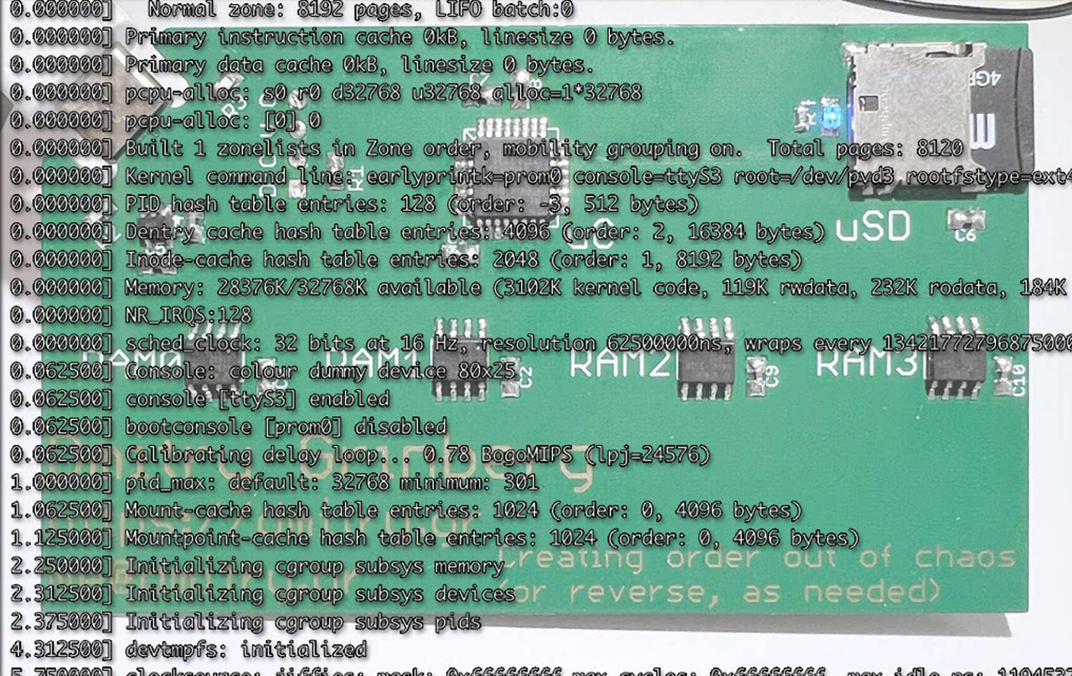
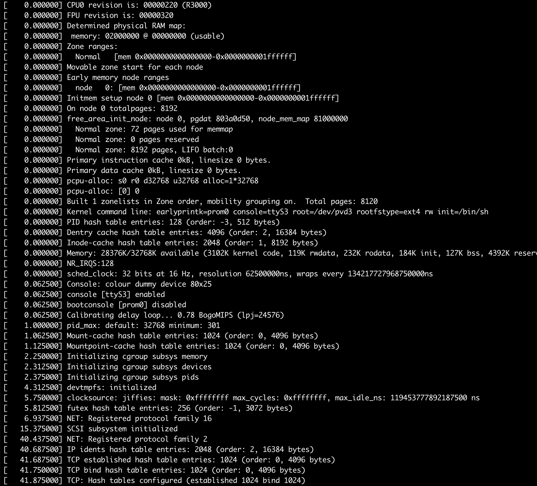
The kernel commandline I pass is rather simple: earlyprintk=prom0 console=ttyS3 root=/dev/pvd3 rootfstype=ext4 rw init=/bin/sh. The first parameter provides for early boot logging via the PROM console, which is useful to see. After the kernel is up, it'll use the third serial port for console. Originally for the DECstation that was the printer serial port, but Linux users on DECstation use that for serial console due to that being the easiest port to convert into a simple serial port. The rest just tells the kernel how to boot. I prefer to boot into sh, and then issue exec init myself, thus the init=/bin/sh
How uMIPS runs
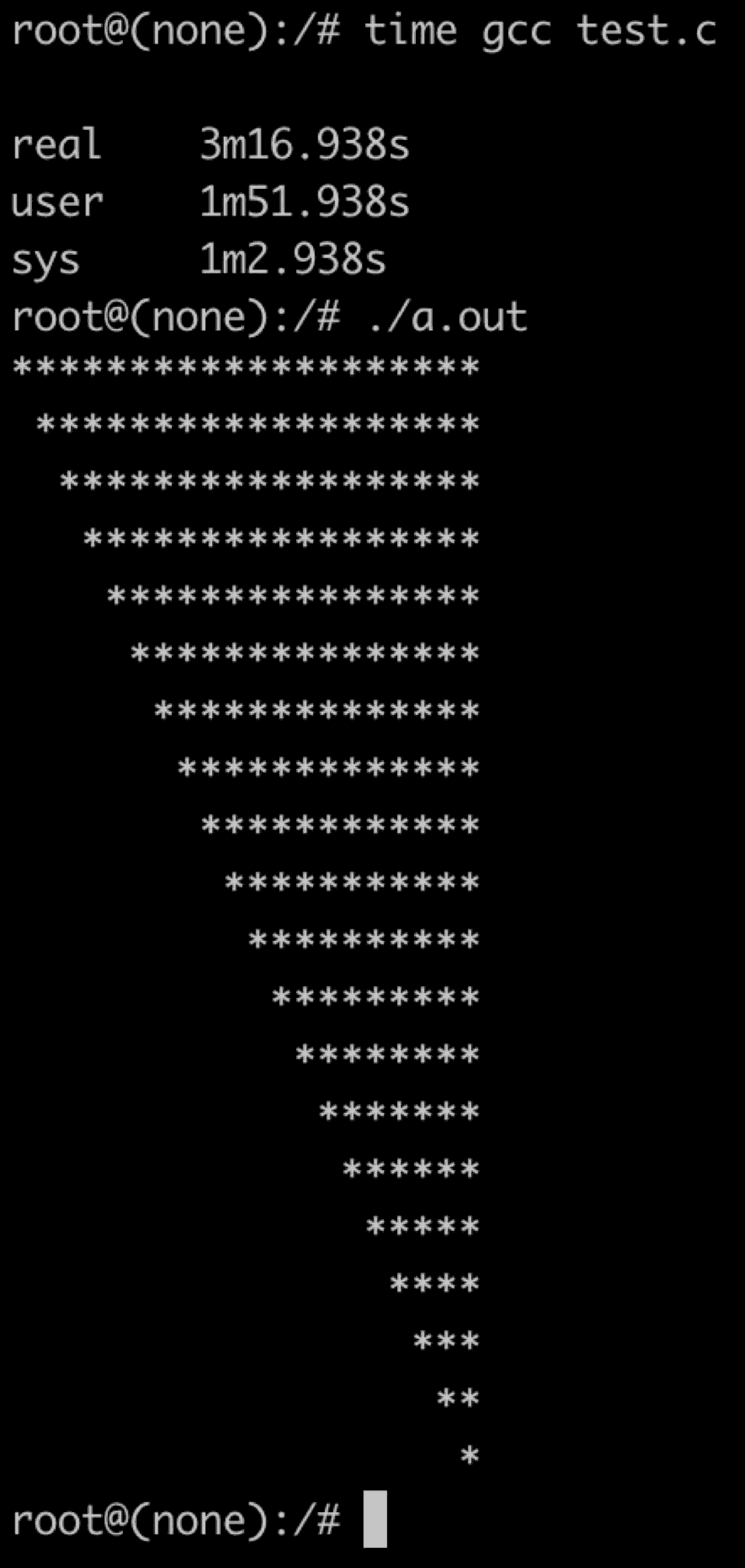
After all the optimizations (which I'll detail in a bit) the effective speed of my virtual MIPS R2000/R3000 on this infernal ATSAMD21 chip is around 900KHz 1.2MHz. The CPU spends around 8% of its time handling timer interrupts, and thus around 0.83MIPS 1.06MIPS of CPU cycles are left for useful work. With this, the kernel takes around 2 minutes to boot and run sh. Executing busybox's init and getting to the login prompt takes another minute. Overall not too bad. Commands reply instantly, or in a few seconds. It takes gcc around 2 minutes to compile a hello world C program, and I estimate that in a few days' time, one could rebuild the kernel on the device itself, copy it to /boot, and reboot into it. Yes, I do intend to try this and time it did do this and it worked!
The emulated real time clock is actually real time, plus or minus the inaccuracies of ATSAMD21's ultra-low-power 32KHz timer. It is ok enough that you will not notice. Try the uptime command.
There is just one thing I did not yet address concerning running Linux on uMIPS. The storage. I said that it is an SD card, but surely DECstation had no SD card slot. However, Linux is open source. I simply created my own very simple paravirtualized disk driver which uses a hypercall to talk directly to the emulator and request sectors to be read or written directly into the virtual RAM. To Linux, this looks just like DMA, except instant. The whole implementation of the driver is under 200 lines of code and can be seen in pvd.patch
Linux changes
I made some changes to the kernel to make life easier. They are provided as patches against the 4.4.292 kernel, and as is a working kernel image. Why that version? Because when I started that project, it was an LTS version of the kernel, and since RAM is short, I wanted the smallest possible kernel, so this was preferable to a later version. The config I am using is available in kernel_4.4.292.config. A config for an even smaller kernel (that requires uMIPS to emulate the full FPU) is available in kernel_4.4.292.config_nofpu
I did a lot of work making the kernel as small as possible. Since Linux does not support paging out pieces of the kernel, every byte of kernel code is one byte fewer available to use for user space. I ruthlessly removed options that were not needed. In the end I got the kernel down to just under 4MB, which is pretty damn good, considering that MIPS instructions are not very dense.
As part of this work, I made a few code patches. For various reasons (cough..delay slots..cough) the kernel can find itself needing to interpret userspace code, or parse userspace instructions. No matter what kernel configs I gave, the code to handle microMIPS (a future MIPS expansion not known in the days of R2000/R3000) was present. It was wasting space and time trying to handle things that would never happen. The patch useless_exc_code.patch removes this code if the target CPU does not support microMIPS
Before I implemented my FPU emulator, I was using the kernel's FPU emulation code that traps and executes FPU instructions. It had a bug. If compiled for a 32-bit MIPS processor it did not properly emulate some FPU instructions that operate on the double type. I believe this is wrong. It was causing crashes in code compiled for R3000. The patch fpu.patch modifies the kernel's MIPS FPU emulator by adding a config option to enable the full FPU emulation even on MIPS-I chips.
Due to the differences between the R2000/R3000 and the R4000 the kernel needs to know at build time which CPU it is being built for. If you attempt to run the wrong kind of kernel on the wrong kind of CPU, it only gets far enough to panic about it. Fine, OK, but then why does this flag not affect a lot of TLB-handling code. Both kinds are always compiled in, despite us knowing at build time with 100% certainty that at least half of it will not ever be of any use? The patch tlbex_shrinkify.patch wraps the useless code in checks for the compile-time-selected CPU type and thus removes some kernel code, saving valuable bytes.
As uMIPS runs with a real real-time clock, I did not want Linux to spend too much time handling timer interrupts. Normally, a 128Hz timer is used on DECstations by Linux. I added options for 64Hz, 32Hz, and 16Hz timer ticks as well. This reduces effective timer resolution, but effectively unloads the virtual CPU from having to spend most of its time handling timer interrupts. The patch clocksrc.patch does this, and the one called kill_clocksrc_warning.patch silences a pointless warning about timer resolution.
If you do build uMIPS with full FPU emulation, there is aso a patch to remove all of the FPU emulation code from the kernel to save a few KB of RAM: fpu.patch.
Improving performance
Instruction cache
One thing the processor will surely do every cycle is fetch an instruction. This means that every cycle begins with a memory access. For us that is a painful subject thanks to Atmel's errata-ridden SPI unit. And not just that, memory translation also needs to happen, and that also takes time. A good way to avoid both of these problems is a VIVT instruction cache. It'll read instructions 32 bytes at a time, and allow us to hopefully often not need to translate addresses or reach for main memory. I allocated 2KB of RAM to this cache. It is 32 sets of 2 ways of 32 byte lines. Whenever memory mappings change, it needs to be invalidated. I do this automatically and thus the running code on the virtual MIPS CPU does not need to know about it. The measured hit rate while booting Linux is around 95%, which is pretty nice for such a small cache. The geometry was determined experimentally by profiling how long a boot takes with various cache geometries. This one was found to be the best.
Improving CPU speed
ATSAMD21 series is specified to run at 48MHz. In my testing they run perfectly well up to 96MHz, with some specific chips able to hit 110MHz. I found no chip unstable at 96MHz, so I decided to just run at 90MHz, for some safety margin. This immediately got me a pretty serious performance uplift. No, it is not really 100%, since (1) SPI RAM is still limited by the SPI speed limit, and (2) flash memory has wait states which had to increase for the larger speed. But this did give me an honest 65% improvement. Still a good start. Now RAM SPI runs at CPU / 6 = 15MHz.
Improving RAM bandwidth
Since I could not make the RAM SPI units go faster due to Atmel's incompetence, I decided to go wider! I can drive four units at once. Given, there is overhead to each read and write command, but still this is faster than one or two. My code initially supported one, two, or four RAM chips, but for simplification I dropped that support and now only support four-channel RAM. Quite the statement eh? This microcontroller has four-channel RAM! The emulator accesses RAM in increments of 32 bytes. The RAM read/write commands themselves are 4 bytes each. This means that for a single-RAM chip situation, reading 32 bytes takes (4 + 32) * 8 = 288 SPI bits. In dual-channel configuration it'll take (4 + 16) * 8 = 160 SPI bits, since the command is still 4 bytes long, but we only read 16 bytes from each RAM , for a total of 32. For quad-channel RAM, we thus have (4 + 8) * 8 = 96 SPI bits to read 32 bytes. This is a 66% improvement from the single-channel case! In reality the improvement is less, since quad-channel mode cannot use DMA at all, so it is a bit slower. Real-life measurement shows that quad-channel mode is a 50% improvement over the single-channel case. But still, given this damn chip, any improvement is an improvement I'll take.
But, why are all the RAM acceses 32 bytes in size? Well, as you see RAM accesses are slow. A typical 32-byte access takes 140-ish SPI cycles, which is around 12 microseconds. If every access took that long, my emulated CPU would be limited to no more than 85,000 memory accesses per second. That is too slow to be practical. Something had to be done. I decided on a cache. Sadly, my microcontroller has a very limited amount of RAM, so the cache had to be small. I evaluated various cache geometries, and found that a 20-set 2-way cache with 32-byte lines produced the best performance uplift for the emulator. It gets a 91% hit rate while booting the kernel, which is a pretty good payoff for 1.25KB of RAM. With a hit taking around half a microsecond and a miss taking around 12 microseconds, adding this cache improved the average memory access by 87%! Yes, this is effectively an L2 cache. Now, how many emulators do you know that have an L2 cache to paper over the terrible performance of their chosen host hardware, eh? The cache allocates on reads and writes, except for reads and writes of precisely 32 bytes in size. Those are passed through directly because they are either SD card access DMA or icache fetches that do not need to also be cached in this cache.
After some more profiling, I rewrote the "hot" part of the memory access code in assembly for some more speed gain. GCC may have come a long way since a decade ago, but it still does not hold a candle up to hand-written assembly. I removed support I had for one and two-channel RAM to simplify the hot path as well. So now you need to populate all four RAM slots for the card to boot. If you populate different RAM sizes, the smallest one will dictate the final usable RAM size. The usable RAM size will always be four times the size of the smallest RAM chip. This isn't a big deal, the DECstation came with 4MB of RAM, and could be outfitted with a maximum of 24MB. This card can be outfitted with 32MB, so you'll be living like a king! That being said, due to the size of the Linux kernel, you're not going to get a successfull Linux boot unless you have at least 6MB of RAM, and uMIPS will refuse to boot if that is the case (eg: if you populate 4x 1MB chip).
Dirty hacks specifically for Linux
Remember how on MIPS the operating system must do its own pagetable walking and filling of the TLB? As you can imagine this happens often. Very often. How could I speed this up without causing any correctness issues? On taking the TLB refill exception, I verify the handler has not changed and matches the expected bytes, if so, I do what it would have done, but in native code, not emulated MIPS. This helps this particular code run quite a bit faster. Correctness is not compromised since this is only done if the handler matches what is expected, byte for byte.
I also mentioned that due to how delay slots work, if a CPU takes an exception on an instruction in the delay slot, the kernel must be able to completely emulate that instruction, or in other way execute it and then jump to the right place? Linux uses the fact that MIPS has no PC-relative instructions, except jumps, and it is illegal to place a jump in the delay slot. How? Instead of emulating the delay-slot instruction, Linux copies it out to a special page in memory, where it is followed by a trap. Linux then jumps there in user mode to let it execute, catches the trap, and then re-directs execution where it should go. Now, if this sounds like a giant hassle to you, you are right. What can we do? Well, if an instruction in a delay slot causes an actual exception (like an illegal access, or a TLB refill exception, or some such thing), not much can be done. But what we CAN do is not make things worse. uMIPS will not deliver IRQs before executing an instruction in the delay slot of a branch. At worst, this will delay an IRQ by a cycle, which makes no difference to correctness. The benefit is that this sort of instruction copying and juggling can be done less.
How to build and use one
Building
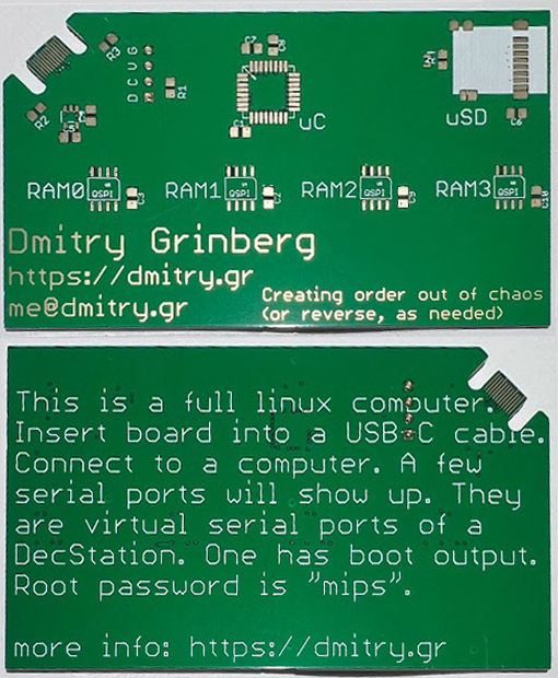
Now, why you really came here. How do you get one? Well, you could try knowing me personally and asking for my business card, I have a few to give out, but other than that, here is how to do it.
You'll need to order the board from a board fabrication place. I am a fan of JLPCB and recommend them. The gerber files I provide come in two flavours. One as you see my card exactly, and one without my name and contact info :). This is a four-layer board, the board house will ask you for layer order, it is: GTL, G1, G2, GBL. At least JLPCB has options to also cover the edge connector in gold for better contact, called "gold fingers" and to grind the board edge to 45° for easier insertion. I suggest selecting both of these options - they are free. Remember to set the board thickness to 0.8mm.
While you wait for the board to arrive, you'll want to order the parts. You'll need four of the same memory chip (I have the links above), an ATSAMDA1E16, an AMPHENOL 11400841 SD card slot, and a MIC5317-3.3YM5TR regulator. You'll also want to (optionally) order an 0603 sized blue or white LED for SD activity light. If you choose to have that LED, you'll also need a 430 ohm resistor in 0603 or 0805 size. Besides that, you'll need in 0603 or 0805 sizes: 2x 5.1Kohm resistor, 1x 1Kohm resistor, 3x 0.1uF capacitor, and 7x 1.0uF capacitor. You will also need an SD card and any SWD programmer capable of programming the ATSAMD chip. There are many out there. Pick your favourite.
You'll need an SD card as well. 128MB is the bare minimum here if you want to fit the busybox-based rootfs in. To fit the debian or hybrid image I am providing, you'll want at least 512MB. You can write the image to the card using your favourite tool for that. On Linux and MacOS that is probably dd, on windows, Win32DiskImager.
Once you've assembled the board, program the MCU with the provided binary software/emu/uMIPS.bin and you're done!
Building from source
You'll want to build a few things. You'll need both an ARM (CodeSourcery) and a MIPS GCC toolchain (I used mips-mti-linux I found online). First, build "romboot", "mbrboot", and "loader". Then, build the kernel. I provided the config, patches, etc. Then you'll want to build the emulator. To build for the MCU, use make CPU=atsamd21(UPDATE: proper target name changed, see updates later in the article). To build for PC, try make CPU=pc. Then you can build the SD card image. You'll want to copy the MBR from one of mine and modify it, then use mkdisk.sh to embed your kernel, mbrboot, and loader. Use a loopback mount to copy in your rootfs.
If you want to run the emulator on PC, there are a few things to note. First of all, Ctrl^C will kill it :). Second, unlike the MCU version, the PC version does not incorporate the rom loader in the binary, so you'll need to provide a pointer to it on the command line. A typical command line is ./uMIPS ../romboot/loader.bin ../disk.wheezy
If you are lazy
For the lazy ones I am trialing selling all the parts and the board together as a kit on tindie. I'll see how this goes. My suspicion is that it'll end up being a giant pain in my ass and not worth the time, but I am giving it a fair shot. EDIT: Apparently not, and not even with a good reason. I quote: Please resubmit for admin approval once you have addressed: Other Reason.. LOL, how about NO? As a sidenote, if anyone knows companies that do this sort of thing for me (sell a kit I designed), please drop me a line by email. If you are really really lazy, I might consider having a batch of these factory-assembled by JLPCB as well. If you are interested, click here and let me know. No promises yet.
Using
I provide a few disk images. The smallest is the busybox-based one (disk.busybox) - it is small, fast, and cool. I built the busybox from source for MIPS-I with as many applets enabled as I could imagine being needed. The second image is a full debian wheezy (last version to support MIPS-I) rootfs. I should warn you that debian's "init" starts around 3000 processes while it boots, so that takes a long time. If you are using the debian disk image (disk.wheezy), I strongly suggest to just mount proc and sys, and do your things in "sh" without running "init", but it will work if you do ... eventually. I also provide a hybrid image (disk.hybrid). It has a busybox shell and init, but has all of the debian binaries, so things not provided by busybox are still there and work, like gcc and vim. This is the "hybrid" image.
Using the LinuxCard is easy, insert the SD card, connect USB-C to a computer, and open your favourite serial console app (minicom, PuTTY, etc), if you do not see the boot log, try the other virtual serial port (two exist). In case of a boot error, the SD card LED will blink in an infinite pattern, you can see the code for details on what various numbers of blinks mean.
Once you see the shell prompt, you can play around, or continue boot to login by typing exec init. After this you'll be able to login as "root" with the password of "mips" "mipsmips". There will also be a login prompt on the second serial port as well. So cool!
Version 2
Booting Ultrix
About Ultrix
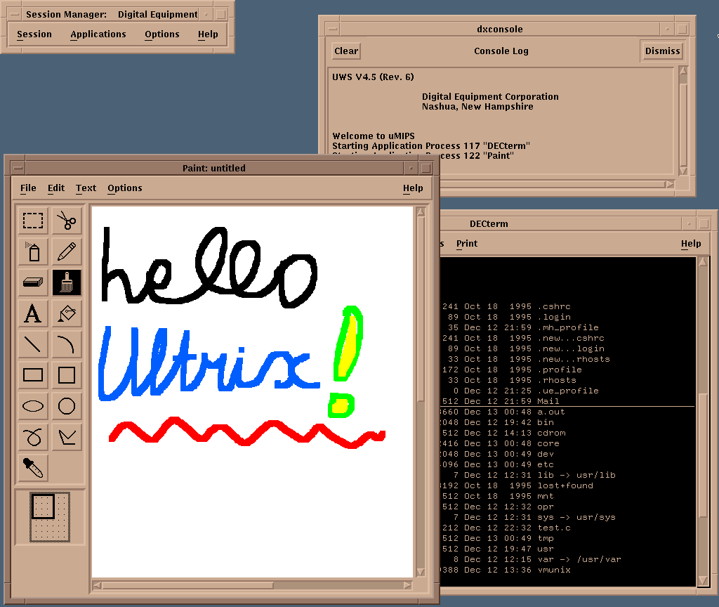
Ultrix is the period-correct UNIX for the DECstation2100/3100. The latest version is 4.5 and with some google-fu you can find ISOs of the install media. It supports the DECstation2100/3100 perfectly, and even has an X11-based UI! The goal of the v2 firmware was to properly run Ultrix on the card. This ended up requiring a lot of work. I had to improve emulation accuracy and implement more hardware. But it did work!
First time booting Ultrix
My first attempts were simple - copy the kernel to my "boot" partition and attempt to load it. It would, of course, not find its root filesystem and panic, but I wanted to see how far I would get at all. The first roadblock was an obvious one - the kernel is not in the ELF format that the linux kernel uses and my loader expects. It is in an older format called COFF. I dug up docs and started working on a parser for COFF. After a little work, I was able to load the kernel and let it run, just to see how far it would go. To my susprise, it got far enough to log some messages to the console! It crashed soon after, when it asked my PROM code for an env variable that I did not know about "scsiid0". Not a bad start. At this point I figured that in a week or so I would have Ultrix booting. It took a little longer...
Ultrix was designed for this machine, and it was designed to support all parts of it. It does not probe for hardware since it knows that a DECstation2100/3100 should have. It assumes that the requisite hardware is there and starts initializing it. This was a problem for me - I still was not emulating the graphics, SCSI, or the network card. Linux has no support for them so I had not bothered.
SCSI
As this was my first time attempting to emulate SCSI, it took a while. SCSI is so over-engineered, the very word "overengineered" does not do justice to just how much so it it. There are messages, commands, statusses, selects and reselects, and oh so very much more. The SCSI chip in the DECstation2100/3100 is a very strange one that DEC designed just for this device. It is called SII or SMII and I found no docs for it other than the official summary in the DECstation3100 specification. It was helpful, as it listed the register bits and values. It was a start. Watching the Ultrix kernel try to access it before it gave up and paniced provided some more help, and reading the SCSI-I and SCSI-II specs filled in the rest. After much work it seemed like the kernel was happy enough to try to enumerate the bus. It would try to select each device in order. Progress!
From there, the next step was to write a virtual SCSI disk. If you haven't dealt with SCSI before, it is rather unlike most sane designs. A sane design would have a host controller be a heavy/expensive/complex machine that talks to cheap simple devices. This makes sense because typically one would have more devices than host controllers. Not here. A SCSI device drives the bus and determines what it does and when. The only thing the host can do is reqest attention from the device. This took a little while to wrap my head around as it is rather backwards. It is actually even more complex since the target device can disconnect from the bus to do things and later reconnect and continue a transaction. It really is quite complex. Luckily, some of that is optional. A device can also reply without disconnecting, and my virtual disk does that. With a lot of work, I was able to figure out the proper state machinery to make Ultrix indeed identify and talk to my virtual SCSI disk. I split the code into two layers. The bottom handles the basics of just being a SCSI device and the top handles actual disk-specific things.
The code later got expanded to support emulating a CDROM too, to allow me to do an Ultrix install from a virtual CDROM. While working on this, I noticed that the bus enumeration is slowing down the boot a lot. The issue is that there is no way to detect that "no device with this ID exists on the bus". One must attempt a select, and then wait for a timeout. This was taking a while since Ultrix implemented a timeout using a loop with a counter (not using the RTC), and at my virtal CPU speed it was taking seconds. The solution was a dummy SCSI device that does reply to some commands enough to be identified and tell the host that it has no media and is of an unknown type. This device is the "SCSI nothing".
The SII controller has 128KB of SRAM for DMA-ing data to/from devices. The idea is that one schedules the transfer and it goes on at its pace, when done, an interrupt occurs and data can be copied in/out of this memory. On the PC, this is simple - i can allocate 128KB of RAM and be done with it. On the microcontroller, I do not have that much SRAM, so I steal some memory from my external memory for this, and present less than the full amount to the virtual OS. This works fine for Ultrix as it probes the memory amount page-by-page. Linux probes in 4MB increments, but I have a patch allow_64K_memory_multiples.patch that changes it to probe in smaller increments so that this memory stealing does not cost 4MB of usable RAM.
Linux has no support for SII SCSI controller, so it continues to use the pvd device.
LANCE
The network card in the DECstation2100/3100 is LANCE. It is somewhat documented in the DECstation2100/3100 specification sheet and I implemented it enought to please Ultrix. It never sends or receives any packets (I can add that later), but it does initialize and interrupt as needed. LANCE has a 64KB SRAM buffer for packets. The PC build of uMIPS fully supports this, the "micro" build of uMIPS will just ignore writes and produce zero reads of this area to avoid wasting 64KB of memory. This works well enough to please Ultrix. Linux has no support for LANCE, so I have no idea if it would be ok with this setup.
ESAR
The MAC address for the network card is stored in a on-board EPROM called the "ESAR" (Ethernet Station AddRess). It lives at the same address as the real time clock, except it is wired to the upper byte of every word, while the DS1287 is wired to the bottom byte. This is a weird thing to do but it works. It does mean that some weird things are possible, like reading both the ESAR and the real time clock registers at once with one read. Luckily this is not usualy done. The ESAR data has some checksums and redundancy (so that its correctness is easy to verify). I implemented an ESAR for uMIPS, assigned the ethernet address 66:44:22:44:66:22 to the device, and provided for all the required redundancy and checksums. Ultrix is satisfied with this.
Memory probing & proper PROM API
While booting Ultrix I notied that it directly probed the amount of RAM in the system. This is strange since Linux simply queried the memory amount from a PROM API that conveniently exists for this. This was actually my mistake since I was emulating a much newer PROM iterface than the real DECstation2100/3100 had, and Linux was happy to use it. The newer standard (called REX) provides the OS a function pointer table with a lot of API. To signal REX support, a magic value is also passed. DECstation2100/3100 predate the REX API and used a different method of providing API to the OS - a table of jumps is placed at known offsets from the start of the PROM in the 0xbfcXXXXX address space. This API is also more primitive, and lacks, for example, the ability to tell the OS how much RAM there is. The pieces now fall into place... My only problem is that I do not have an ability to have a huge PROM, as I wrote earlier. I needed another method to offer this API. I decided to indeed have this jump table, but redirect all the jumps to an address in the RAM area reserved for the PROM 0x80001000..0x8002ffff. You'll recall that my OS loader loads there. Now it can provide this PROM API, just like it did the REX API. Cool! Testing Linux also shows that it happily uses this API properly as well. It is, of course, now also forced to probe the RAM amount. No big deal. I did find a bona fide bug in the kernel here! While it means (as per comments) to probe for a maximum of 480MB of RAM, but actually only probes for up to 30. The fix is in fix_mem_limit.patch.
Ultrix Loader
At this point, the kernel was loading far enough to panic about not finding the root filesystem, so it was time to figure out a good way to make this work. The problem is that Ultrix uses a completely different partitioning system than the well-familiar MBR I had been using. The Ultrix "disklabel" allows for 8 "partitions" but with some assumptions, like that the first (caled "a") is always the rootfs, the second (called "b") is always swap, the third ("c") always covers the entire disk (yes it does and is expected to overlap others), and another one ("g") is /usr. Now, if this was not fun enough yet, the partition table itself is expected to be inside the rootfs partition, and a whole lot of tools (including the installer) assume that this all starts at sector zero. Fun, eh?
I spent a lot of time trying to figure out how to make the installer be happy to not start the rootfs at the 0th sector, but this was a lost cause. A large number of scripts involved assume that both the "a" and the "c" partition start at zero. The kernel also has similar assumptions. With some patching, I got it to work with an offset, but this was not a good approach. I decided to see if I could live with how Ultrix does things, instead of trying to force it to do things my way. Even though the rootfs and the partition table both start at the 0th sector, they both reserve some space up front for "boot code". Specifically, the first 16 sectors (8KB) are always free. I decided to simply place my loader there and teach it how to understand the Ultrix disklabel. As part of this work, I refactored the loader into a few pieces. One part was a partition table handler. There is an option for MBR, one for Ultrix, and one for NetBSD disk labels. One of these (build-time determined) is linked in to the loader, as needed. Another module was a binary loader. Two exist: ELF for Linux and NetBSD, and COFF for Ultrix. Same as before, only one is linked into the loader, as needed. The third modue is the filesystem driver. There is one for FAT12/16/32 (used for my Linux boot sequence), one for old UFS (for Ultrix), and one for modern UFS (for NetBSD). Again, just one is linked in, as needed.
The cool part now is that I can mix and match these pieces as needed to create a loader for the OS I want to boot. The Linux loader is thus FAT + ELF + MBR, for Ultrix, the loader is UFS.old + COFF + Ultrix disklabel, and for NetBSD, it is UFS.new + ELF + NetBSD disklabel. I was too lazy to implement proper CD-booting, so installing Ultrix is a bit weird. I make a disk image with just the installer kernel (extracted from the CD), in a FAT partition, attach the CDROM to the emulator, and then boot. The installer will then re-partition the disk. For this, yet another loader combination is used: FAT + COFF + MBR. The modularity pays for itself!
Making Ultrix work
Framebuffer
Once I had the Ultrix kernel booting properly, at least in the PC build of uMIPS, I really wanted to get the GUI working. Who wouldn't‽ The framebuffer came in two varieties for this machine. There was a monochrome one and a 8-bit color one. They both supported hardware cursor as well. I implemented most of the normally-used modes in the cursor hardware, but not any test modes. I emulated both the framebuffer types and they both work! The 8-bit framebuffer can display up to 259 colors onscreen at a time, out of a 24-bit palette. That is not a typo. The display itself can display 256 colors, and the cursor has its own 3-entry palette, which need not use any of the same colors. The resolution is 1024x1024 in memory, and 1024x864 onscreen. The remaining memory is free for the OS to use however it wishes. I steal memory from the main RAM, same as for the SII buffer. 128KB is used for the mono framebuffer, and a whole megabyte for the color one. The palette is also stored in stolen ram (just about a kilobyte).
Mouse, Keyboard, ... and Tablet
Of course, to make this work, I also had to make the keyboard and mouse work. They talk to the DECstation via serial, and the protocol is somewhat known, from various shreds available online. I was able to put together a passable keyboard emulator rather quickly. It is not a dumb keyboard. It has regions of keys, a bell, some lights, and can support differing autorepeat settings per key group. It is actually pretty cool. The mouse is a pretty basic one, with three buttons. I got that working rather quickly. The problem with emulating mice is a well known one - they are relative device, and most OSs apply acceleration to the mouse as you keep moving it to allow for better reach. Now, if you are running another OS, and passing these accelerated movements to it, it will re-accelerate them even more. This ends up being a mess. This is why most virtualization solutions prefer to load an absolute-pointing-device driver into the guest. I was not prepared to hack up Ultrix or find a way to load a different mouse driver in it. But then I noticed that DEC wrote about a "graphical tablet" that they were selling, that hooked up to the mouse port. Could it be that Ultrix supports this? Yup... Ultrix does. I wrote an emulator for the tablet and it worked wondefully - no more over-accelerated mouse for me! Sweet!
Patches
Ultrix assumes that it is booting on a real DECstation2100/3100, and that includes expecting the CPU to have caches. My virtual CPU does not expose caches to the guest OS, and while Linux handles that fine, Ultrix does not. It correctly probes the cache and finds its size as zero. But there is a logic bug in r3_kn01flush_cache, where if the cache size is zero, it gets into an almost-infinite loop. As uMIPS exposes no cache, it makes sense to patch the function away into just a return. There is another function of interest: kn01delay. It is used for short busy-wait delays when dealing with hardware. All of our virtual hardware is instant-fast, and thus no delays are needed. As long as I am patching a kernel, might as well make it faster. There is also a third area of interest - the periodic timer. In Linux, I was able to change the tick to 16Hz, but I cannot build Ultrix from source, so I cannot modify it easily. Ultrix uses a 256Hz tick. At that rate, on uMIPS hardware we'd never get any useful work done while only handling interrupts. I attempted to patch Ultrix to use a 16Hz timer and account for it correctly. This does not work - there are mathematical errors that happen. 64Hz works, but that is still too freqent for the uMIPS hardware to be usefully fast. I ended up patching the init code to set the timer to 16Hz, but accounting code to act like it is 64Hz. This means that "realtime" in Ultrix runs 4x slower than actual real time, but this is not really a big deal. Just keep in mind that a sleep 1 will delay 4 seconds and not 1.
So how does one even apply such patches? How does one find the proper places to patch? I spent a LOT of time learning about the barely-documented symbol format used in the Ultrix kernel. It worked! I made a working parser for it and was able to properly identify the symbols I needed and to patch the places that needed patching. This was good until I realized that while the installer kernel does ship with symbols, the kernel installed for first boot does not (after first boot, the kernel is recompiled again, with options you choose, and that version DOES have symbols). No symbols means that I cannot use them to find the proper locations to patch. I decided on a different method - binary matching. Look for the proper set of bytes in a row, it should be unique in the kernel. If you find just one case - it's the right one. To save space in the loader (as it is limited to 8KB), I compress the "pattern to look for" cleverly. Cool. This is the final approach I used and you can see it in loadUltrix.c.
Improvements in the emulator
USB improvements
After a lot of googling, I learned about interface association descriptors. Turns out that without them, windows will not load the USB CDC-ACM drivers for a device. After adding them, Windows would properly load the driver and it would show up as a COM port. I also learned about the peculiar ways that Windows enumerates devices. Sometimes it'll ask for a descriptor, stating that it'll accept 64 bytes, but after receiving just one 8-byte packet it will reset the bus. This was breaking my USB code, and this is now fixed. Windows now properly supports uMIPS and shows it as two COM ports. Sweet!
More perf improvements
At the end of emulating every instruction, the emulator jumps "to the top", fetching a new instruction to execute. In most cases before this a check is done for whether there is an interrupt pending. This jump was done using a BL - the only long-distance branch available on the Cortex-M0. It takes 3 cycles. The check involved loading a byte from memory (2 cycles), checking if it is zero (1 cycle), and jumping to the interrupt exception creation code if so (1 cycle if not - the common case). That means that the entire "jump and begin handling the next instruction" step took 6 cycles. I wanted to make it faster somehow. I decided that if I could free up a register, I could. Some reworking freed r11. There is a parameter you can pass to gcc to tell it to not use a given register in any C code it compiles: --ffixed-r11. Now that this register is not being used by anyone ever, we can do the clever thing. We keep the address of the "load next instruction and execute it" label in it. Now we can jump to it using just bx r11. This takes just 2 cycles - 4 cycles saved per virtual instruction - a significant speed up. But what if we do have a virtual interrupt to report? Whenever we have one to deliver, we just set r11 to point to the "report a virtual interrupt" label, and whenever the current virtual instruction is done being emulated, the interrupt will be reported and r11 will be reset. There is a bit more machinery needed to make this work, but this is it in general terms, and it does work!
I also changed how the TLB hash works (from a table of 32-bit pointers to a table of 8-bit indices) to make the table and each entry smaller (from 24 bytes to 16). This saved a bit under a kilobyte of RAM, which I was able to allocate to the L2 cache. It has now grown from 1.25KB to a full 2KB for a measurable perf improvement!
Removing the TLB refill fast path
For Linux, I had implemented a fast-path for the TLB refill code - it executed in native code what he TLB refill handler would do. In my measurements it slightly improved performance. With all the other performance improvements I had implemented, it no longer offered a measurable improvement. Plus, it did not help Ultrix at all, by definition. Removing it saved flash space and removed complexity. Less complexity is always better. It is gone.
Cache geometry changes
Previously, when profiling to find the best L1i geometry, I used the Linux boot process. I decided to try harder. Now I profiled that, gcc compiling some code, a few other Linux binaries, Ultrix boot, and some Ultrix userspace utilities. The result of this investigation was that a direct-mapped L1i is slightly faster than a 2-way L1i cache. The hit rate goes down slightly, but checking only one cache line instead of two speeds up the checking enough to make up for it. I thus reconfigured the cache as a direct-mapped cache.
Serial improvements
Previously, the emulator would wait a fixed 20ms to send a character to the PC before giving up. I changed this to a permanent wait for the main console. This allows the user to not miss any output if they close their terminal. The emulator also shows its version up front, since it will definitely not be missed now. As of firmware v2.1.1, uMIPS also shows the RAM configuration in terms of the number of chips, each chip's size, and the bit width of the per-chip interface.
More Floating Point Unit work
I had already implemented a full virtual FPU, but now I wanted to see how necessary it really was. I knew that Linux would run if I emulated no FPU at all and would emulate it. I wanted to see if Ultrix would. It did not - it crashed with an invalid instruction trap in the kernel. This was not all that surprising. Once again, it was compiled for a particular machine - a machine that had an FPU. Its assumption that an FPU exists was sane. But there was still more to investigate. The MIPS spec says that the FPU may refuse to execute any instruction if it is not sure that it can perform it perfectly accurately. Since the spec is not clear on what that really means, basically any OS running on such a MIPS chip must implement a complete FPU fallback, capable of emulating any FPU instruction. But then why am I hitting an exception?
The trick is that the FPU must still exist, it must refuse to do math. This is strictly different from not existing at all. I thus implemented a "minimal" FPU. It implements the instructions to identify itself, move data in and out of the floating point registers, and load and store floating point registers to memory. Any attempts to do actual floating point math report a "coprocessor usage exception" which is the proper way for the FPU to refuse to do math. This worked correctly for Ultrix - it now will not crash at boot, all applications that do floating point math still run, with the kernel emulating the math. I checked and Linux also supports this setup. Thus uMIPS now has three FPU configs that it can be built with: full, minimal, and none.
A bootloader
As I handed out more and more of these cards, the update story needed to be improved. Not everyone has a CortexProg lying around to reflash the firmare. I decided to make it simple and require as little user interaction as possible. The bootloader is just under 3K, I allocated 4K of flash to it, and relocated the main firmware to start 4K into the flash. So, how does it work? At boot, the bootloader will minimally initialize the SD card, attempt to find a FAT16 partition on it, see if it contains a properly-sized file called FIRMWARE.BIN on it, and if so, the firmware will be flashed from this file. On error, the error number will be blinked out on the LED, repeatedly. On success, a varying-frequency pattern of the LED will be repeated forever.
If the card fails to be initialized, if it fails to mount, if the update file does not exist, or if it is not correctly sized, the bootloader will continue to boot the existing firmware, if any exists (some sanity checking is peformed). This means that when you insert a card with my Linux image or the Ultrix image, all will work as expected. Only FAT16 is supported, so some partitioning may be required on larger cards. I can live with that.
Hardware improvements
v1.3 hardware

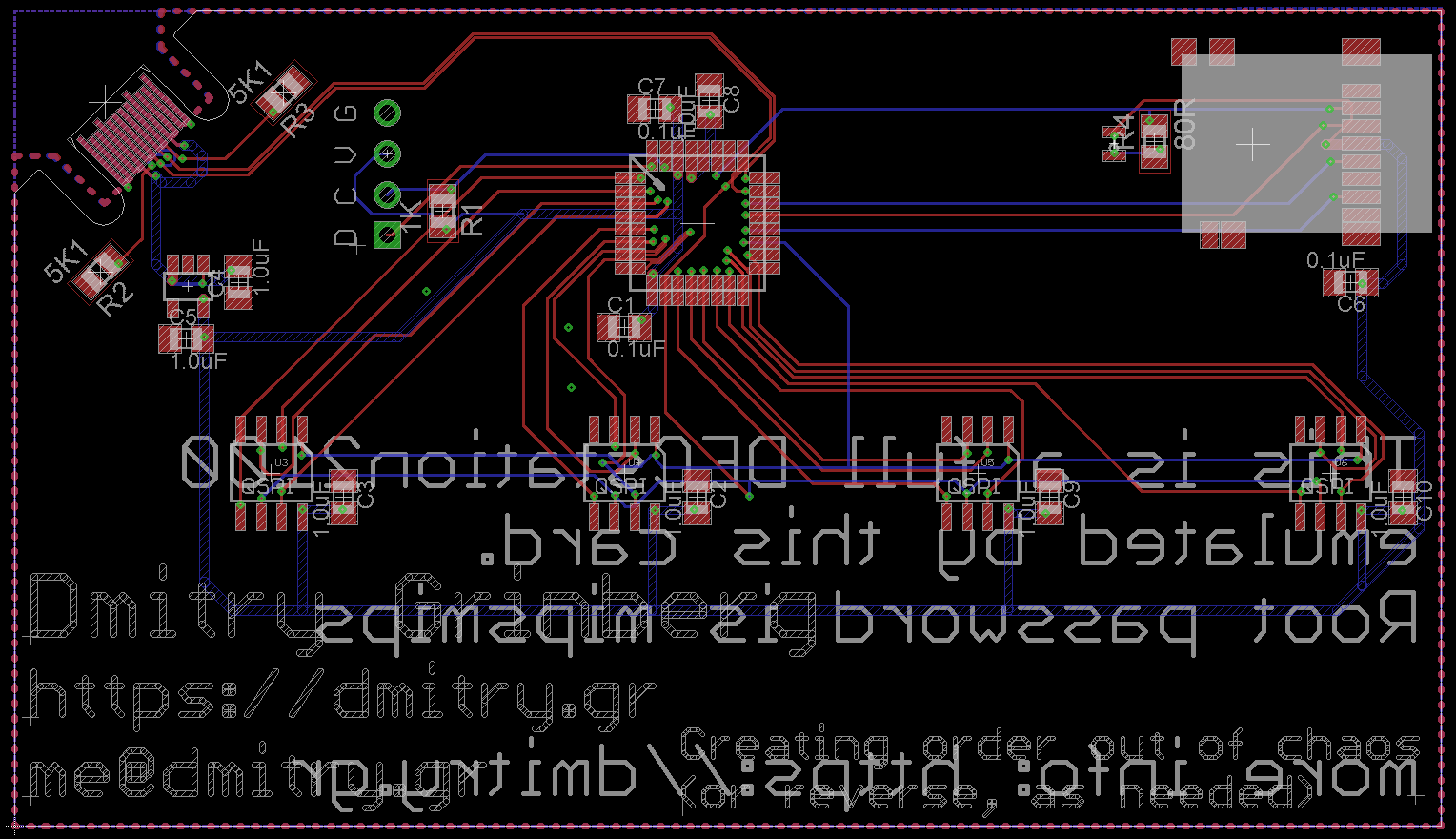
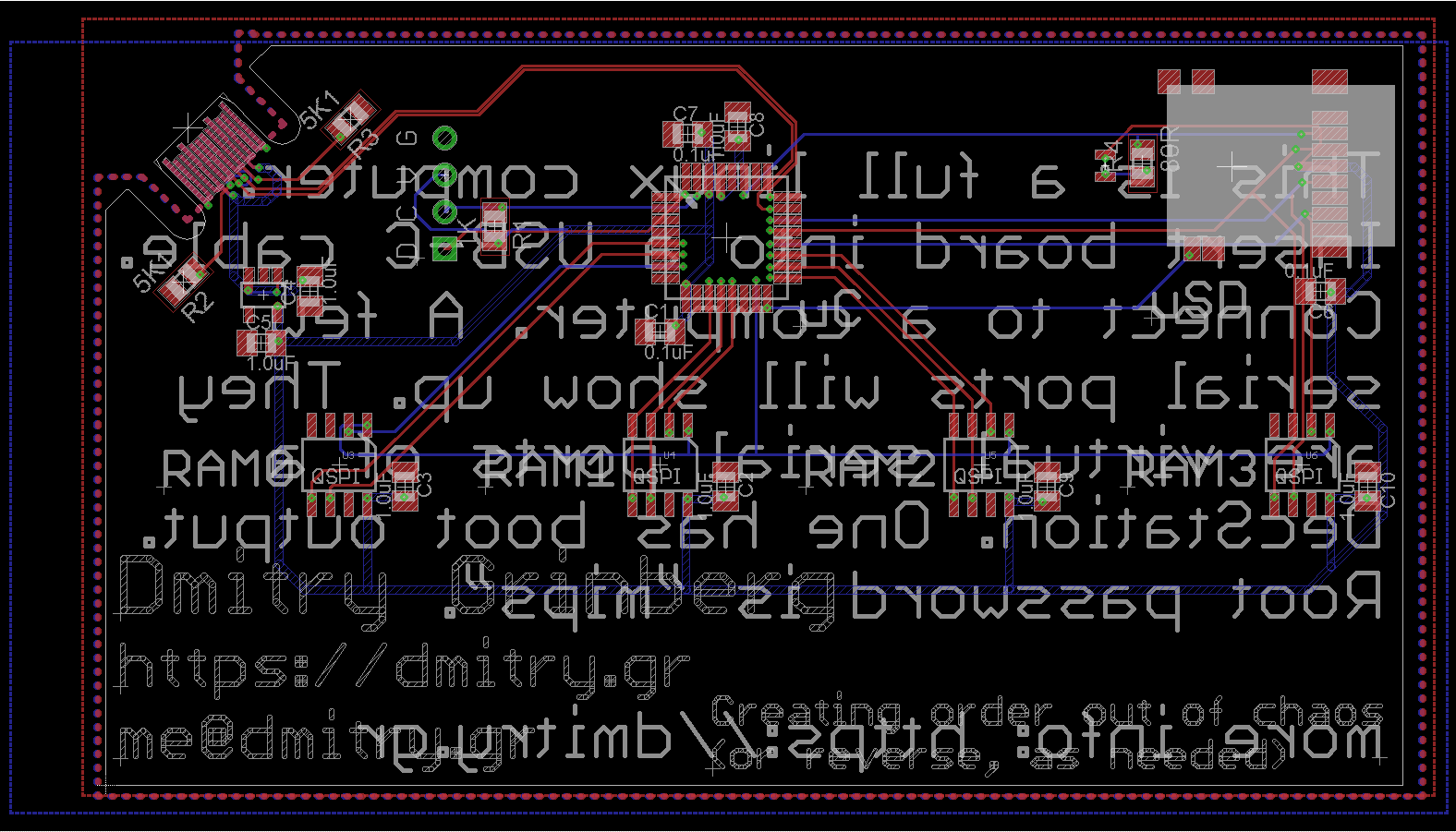
After reading my original article, a few people wrote in (including in the comments section here, on twitter, and in email) to suggest that maybe I should entirely abandon the shitty SPI units in this chip. Initially I was worried that the SPI unit speed issue was really an IO port speed issue, but a quick test showed that I could toggle a pin at half my CPU clock reliably and get nice square edges. I prototyped bit-banging SPI on the existing board to see what speeds I could attain and it was promising. I then laid out a new board, with different wiring, to allow me to actually use QSPI mode. The images for the new schematics and the layouts are the ones you see here!
The ATSAMD21 series features a single-cycle IO port. This optional Cortex-M0+ feature is pretty useful for bit-banging. It really is single-cycle-fast. Normal loads and stores take two cycles minimum on a Cortex-M0+, but ones targetting this kind of a unit take just one. That is how I could toggle a pin at half the cpu speed for my test that I had just mentioned.
With big-banging, the trick is to do as few operations per cycle as possible. Given this, it would be ideal to do minimal bit-twiddling. It would be super-awesome if I could wire up the four QSPI chips to GPIOS numbered 0..15, allowing me to just read/write the bottom 16 bits of the GPIO port for simple access. Alas, this was not meant to be. This chip has no contiguous 16 GPIO pins wired to the physical pins, so I settled for wiring RAM0 to GPIO0..3, RAM1 to GPIO4..7, RAM2 to GPIO8..11, and RAM3 to GPIO14..17. Since I will be driving them all together, the clock and chip select lines are all wired together. After all was said and done, after the assembly was coded, and the dust settled, I was able to get around a 9MHz clock speed on average. Since the command and address are also sent 4-bits-wide, the speed increase is nice. Previously (using hardware SPI) it took around 8 microseconds to read/write 32 bytes, now it took just under 4 microseconds. A nice speedup.
An astute reader might notice that the first three RAMS ARE on consecutive GPIO pins. Three is not of much use to us, as it is not a power of two, but two... Yes indeed using only two RAMs i can attain faster speeds (but at half the width). The actual time to read/write 32 bytes is around 5 microseconds. Given this, I decided to re-add the previously-removed support for using less than 4 RAMs on the board. And I did. The newest firmware now supports 1, 2, or 4 RAMs populated on the new boards. I then went futher, and re-added this support for the old boards. That is not as well optimized - it is in C, not ASM, but good enough to play with. This will allow assembling these boards cheaper. Plus, Ultrix happily boots and runs in 4MB (it does need 5MB to start the GUI though).
And old hardware too
I did not want to maintain two separate-but-almost-equal branches of code for the older v1.2 hardware and the new v1.3 hardware. There was also no easy way to tell them apart in software from first glance. But a bit more investigation does provide an idea. The wiring for the RAMs is different enough that we can try each way and see if we detect a plausible RAM chip. It helps that not having RAM0 populated is never supported. This is precisely what I did, in fact. I tried both configs and see which produces a valid-looking ID from RAM0. From there, all four RAMs are probed, identified, and a configuration is picked.
Support for less than 4 populated RAMs raises a few interesting questions. For speed, all RAMs are treated as if they are the same size, so the size of the smallest RAM determines the total amount of available RAM. This is because I stripe the data across them, of course. So, what if RAM0 is populated with 8MB, and RAM1 with 2MB? We could use just RAM0 and get 8MB of RAM or we could use both and get just 4MB, but faster, since more RAMs in parallel is always faster. I decided that more RAM is better than faster RAM, so in case of such conflicts, more RAM is always chosen. When there is a tie, the faster configuration is used, eg: 4MB, 1MB, 1MB, 1MB RAMs populated add up to 4MB in both the x1 and x4 configs. In this case the x4 config will be chosen and all the RAMs will be used.
Building from source (updated)
The emulator
A new parameter called FPU is now passed to uMIPS build to specify the FPU type desired. Options are: none - no FPU at all, Ultrix will not like this but it makes the smallest image; minimal - an FPU that can store values but refuses to do math - Ultrix and Linux will support this, it is slightly larger; and full - a full FPU that does all the math - the fastest option that bloats the Cortex-M0 image by 17KB or so.
The loader
To build the proper loader, pass the BUILD parameter to make. The options are linux, ultrix, ultrix_install, or netbsd. The install loader is just for clean installs, which you have no reason to do since I already did it for you. The netbsd one is to attempt boots of NetBSD on this machine, as it is supported by NetBSD. The proper loader needs to be built and integrated into a disk image for a working system.
The integration step also changed, mkdisk.sh is gone, replaced by a number of different tools, depending on the intended system. They are: mkdisk-linux.sh, mkdisk-netbsd.sh, mkdisk-unix.sh, and mkdisk-unixinstall.sh. Unix here refers to Ultrix, of course. The scripts are small and self explanatory. Open them for more details. They all operate on a disk image called "disk"
To enable GUI in Ultrix, the env variable "console" needs to be properly set. In loader.c, find it and set it to "0,0" for text mode or "1,0" for console mode.
Further Updates
Firmware v2.1.1
In this version, BBQSPI memory access sped up by 11% for 4-chip case, 6% for others. Ram config shown on boot.
Firmware v2.2.0
In this version, the bootloader was updated to better support other ATSAMD21 parts, including those with more flash & RAM. It now also exposes a version byte at offset 0x08. The previous bootloader was version 0x10, making this one version 0x11. The version will be shows on the serial console at boot now.
Also, as ATSAMDA1E16 is now apparently out of stock everywhere, I added support for ATSAMD21E17A-AU/ATSAMD21E17A-AUT. The sad news is that this non-automotive part does not overclock nearly as well. It gets unstable much past 76MHz, so I decided to clock it at 72MHz. It does have more RAM (16KB), which allowed me to allocate a lot more memory to L1i and L2 caches. In most measurements, the performance loss due to lower speed is papered over by the gains of larger caches.
On the topic of performance, I also rewrote the L2 cache code in assembly for speed and size gains. The speed gains are significant. For extra speed, there is now an option to move the actual access functions to RAM (which is faster than flash). This gains an extra 8% speed, but at the cost of using RAM. On the old 8KB-of-RAM parts this is not always worth it, since it necessitates shrinking the L2 from 2KB to 1.625KB to make space. On the new 16KB-of-RAM parts, though, it is we;ll worth it. It should be noted that there are 6 variants of RAM access low level functions as there are 2 possible access types (SERCOM or bit-banged) and 3 possible chip counts (1, 2, or 4). Only the ones you plan to use need to be moved to RAM. Others will still work from flash, if you want to make a universal firmware. The firmware I provide now moves the 4-chip bit-banged functions to RAM for ATSAMD21E17. See RAM_FUNCS_IN_RAM in the Makefile and the contents of spiRamAtsamd21.c
While moving functions to RAM, it is easy to accidentally use too much RAM and end up with random crashes as stack collides with data. These are a pain to debug, so I decided to improve this experience. As an option in the Makefile, there is now ability to enable STACKGUARD. What does this do? As the very last word in the pre-allocated RAM (and thus the very first one that stack would overflow over) the code will keep a magic cookie, whose value depends on the current ticks.hi value. This value is checked and updated in the SysTick interrupt which happens every 16 million cycles. If the check fails, an error will be blinked out the LED and the execution will be halted.
Starting with this version, the proper make incantations are now make CPU=atsamda1e16 and make CPU=atsamd21e17
The downloads have been updated with the new code and binaries for both chip types. They can be updated using the bootloader and an SD card
In conclusion
Acknowledgements
I send a great many thanks to my cats for cutely lying under my table to keep me company during the many hours spent on this project. I send a giant, Mount Rushmore-sized middle finger to Atmel for this sorry excuse of a chip. UPDATE: I even gave up on using the SPI units here, so at this point, I send two of those fingers. Thanks for nothing, Atmel.
Downloads
The source code, gerbers, schematics, and all else except the disk images can be downloaded [here]. The license on my code is simple: free for all non-commercial use, including using as your own business card. For commercial use (like if you wish to sell kits of this project), contact me.
The disk images (updated) are large so I have no desire to host them on my site, so: [Google Drive] or [MEGA].
Comments...
