Table of Contents
The givens
Initially...
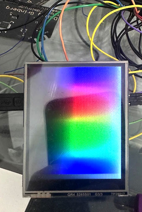
I was searching for a display with at least 160x160 resolution and a resistive touch screen that would mate easily to RaspberryPi pico for my rePalm project. There were not many, actually. But I did come across this display at Waveshare - a 2.8inch 320x240 full-colour LCD. Without much further looking, I ordered a few and started planning the code to drive it. The goal was to have a framebuffer supporting 1, 2, and 4 bits per pixel greyscale, 8 bits per pixel indexed colour, and 16 bits per pixel full colour modes, while getting touch data in realtime. As this display does not support indexed colour or greyscale, that would need to be locally synthesized somehow. Additionally, I saw a few different articles out there about how people drive this display, and they were all atrociously inefficient, so I figured I could publish a way to do it right and save everyone else the trouble and pain. Presented here is a very fast driver for this display supporting 1, 2, and 4 bpp greyscale, 8-bit indexed colour, and 16-bit fullcolour modes on the whole display or any rectangular subset of it. Touch data is copied to a memory location for your perusal at your leisure automatically, and if you wish, you can even do tear-free page flipping and get VSync interrupts. No CPU cycles are used at all! A real, proper driver. So, why is driving this display properly a pain? Well...
The issues
Waveshare provides sample code for this device. It is beyond bad. The code assumes that you want to actively draw to the display - literally send pixels or rectangles of data to it manually, whenever you want to draw. I have no idea who'd actually do this sort of thing. It is pure insanity both in terms of code size and in terms of speed. The various articles I found from others on using this display did equally insane things, like DMA-ing a line of data at a time, and using the CPU to set up the next xfer. Oof... Luckily the datasheet for the LCD controller, the datasheet for the touch controller, and the schematic for this board are available. Now, normally you'd just set up a repeating DMA to the SPI controller to send the data to the screen repeatedly and call it done, but not this time. The idiotsjokers who designed this board apparently never considered that someone might want to actually use it. While there is a wide abundance of pins to use, they stuck the display, touch, and SD card all on the same SPI bus. They did provide some solder bridges that can be used to switch the SD card to its own bus, but the touch controller and the LCD are stuck sharing the bus. So, if I were to set up a repeating DMA to the screen, there would be no time to talk to the touch controller. I could use a timer to schedule the DMA, and do touch sampling, but that requires CPU involvement. I wanted a solution that used no CPU at all.
PIO
As I was using the RP2040, I decided to see if I could use PIO to solve this problem. Each PIO state machine is rather simple, containing only 2 general purpose registers, 2 shift registers, and space for at most 32 instructions (actually 32 are shared between groups of 4 state machines). They lack any ability to do math. The state machines can, however, send and receive interrupts, including from each other, and can send and receive data via DMA. I figured that with some effort I might be able to cobble together a working CPU-free driver for this display and touch screen.
Towards a solution
The math
First, some math. The stated maximum SPI clock frequency that this display controller chip supports is 62.5MHz. It takes 16 bits to send a single full-colour RGB565 pixel, and we have 320x240 of them. This means that the maximum possible framerate in the ideal conditions is 62.5e6/320/240/16 = 50.86fps. We'll not reach this. In ideal conditions, sampling X, Y, and Z from the touch controller takes 51 cycles, and the maximum possible SPI clock rate when talking to the touch controller is 2.5MHz. This means that a complete X, Y, Z sample takes 51/2.5e6 = 20.4 microseconds. Since touch is noisy, it needs to be sampled rather often to provide enough samples for smoothing. I targetted 400Hz. So, per second touch sampling would steal 20.4*400 = 8.16ms. With that removed, our new maximum possible frame rate for screen updating is (1-.00816)*62.5e6/320/240/16 = 50.45fps. This accounts for 16bpp mode as well as the 8bpp indexed colour mode (since we'll be sending it 16bpp data). For the greyscale modes, we'll put the display into 12bpp mode to save on SPI traffic. For that, our maximum possible framerate will be (1-.00816)*62.5e6/320/240/12 = 67.26fps. Not bad. In theory... Now, we just need to sort out how to make it all work.
The 16bpp mode
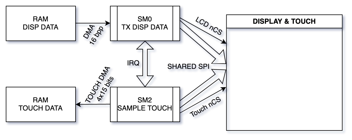
The 16bpp mode is the simplest, since the display natively supports RGB565 fullcolour mode, so it made sense to start there. Things are pretty easy here. State machine 0 (SM0) here will ingest data, 16 bits at a time, and shift it out MSB first SPI-like to the display. But, remember, we need to sample touch. New plan. We set the X register to some value, say 2560. We then lower the display's nCS, and send it data. We send pixels until we have sent X of them (this is approx 1/30 of a screen's worth of pixels). After this we raise the display's nCS and signal an irq to State machine 2 (SM2). We then wait for an irq back from it. SM2 was waiting all along. It lowers the touch controller's nCS, gathers a sample, raises touch controler's nCS, and signals an irq to SM0, which continues sending data to the screen. This should work and it does.
We'll need some DMA channels to support this. Channel 0 will send raw screen data to SM0, when done, it will trigger channel 1, whose only job will be to re-start and re-trigger channel 0. Thus the display is constantly refreshing from our framebuffer. Touch is a bit more complex. To gather our samples we need to send three commands to the chip, and get three 12-bit responses. DMA channel 3 will program channel 2, in sequence, to first send the 3 commands to SM2's TX buffer, then receive the 3 data points from SM2's RX buffer, then reprogram channel 3 so that we can do this again in a loop. In actuality we'll be receiving four data points, not three. More on why later. In any case, with these four DMA channels and two state machines, the 16 bit mode works. We get touch data DMAed to RAM and display image DMAed from RAM, all with no CPU involvement at all. Channel 2's completion interrupt can be used to tell us when a new sample has arrived, if desired.
Touch
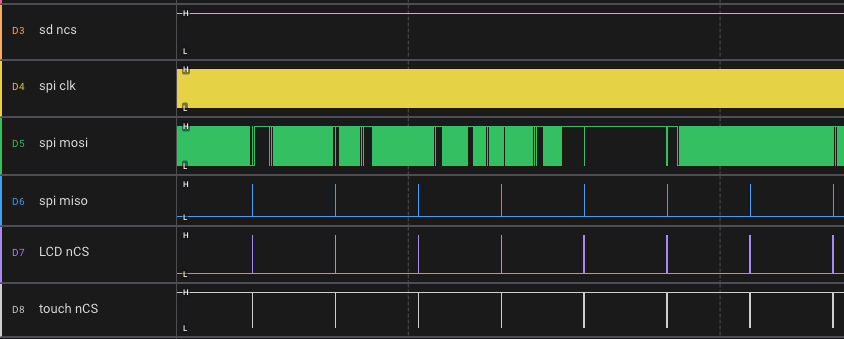
The touch controller, in the best case, can produce a new sample every 15 cycles. We'll try to go for that mode. This does not mean that we can get three samples in 45 cycles. It means that in an infinite stream of samples being done, a new one is ready every 15. In reality to gather three samples, 51 cycles are needed. A new command starts every 15 cycles, and after a delay of 9 cycles, a 12-bit reply (sample) may be read, the next will be 15 cycles after that one, and so on. All this counting is getting rather complex, though. This would waste a lot of PIO instructions. But there is a better way. 51 = 17 * 3, so if I prepare the command bitstream, slice it into three 17-bit words, and enable auto-pull, the PIO code need not do any counting in the TX path, just OUT a bit at a time. This will not work for receive, since each sample would end up shifted by a variable amount. Instead, we really want to sample 15 bits at a time. So we note that 51 = 15 * 4 - 9. Thus, we can configure our PIO code to auto-push every 15 bits, pre-load ISR with 9 bits of zeros up front, and IN a bit at a time. This will produce four 15-bit samples, the first containing all zeroes, and the next three containing the data we wanted (X, Y, Z). Since each PIO SM has a 4-word FIFO for TX and same for RX, we can first load the TX fifo with our commands, then wait for RX using the same DMA channel, as described above. Awesome! Here on the right you can see how it looks when zoomed out - the display data is occasionally interrupted to sample touch, but most of the SPI time is used to send the data to the display, as intended.
The 4bpp mode
This display does not support any greyscale modes. The lowest bits-per-pixel that it can support is 12, in RGB444 format. That mode is precisely what we'll have to use to create our 1bpp (B&W), 2bpp (4 greys), and 4bpp (16 greys) modes. We could, of course, easily do this by taking our framebuffer, fetching every 4 bits sequentially, calculating the proper 12-bit colour, and sending that via SPI. However, the goal is to do all this with no CPU involvement. Luckily, we can. Here is what we'll do.
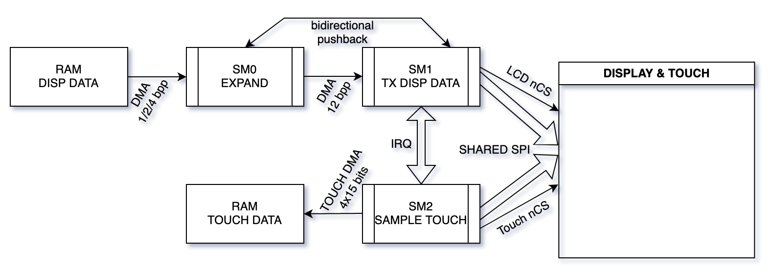
SM0 will be fed (by DMA) the 4bpp data from RAM, 32 bits at a time. It will shift off 4 bits from the low end into a temporary variable. Shift that variable in 3 times, and output those twelve bits. Thus, SM0 simply expands the incoming pixel data into 12-bit display data. We can then set up a DMA channel to feed SM0's output to SM1, which will shift out 12-bit words to the display. After some numbers of pixels it'll give the touch controller some time to sample touch, and repeat forever. There is a couple of issues to consider here. First of all, despite each pixel being 12 bits in size, the display will not accept non-integer-number-of-bytes-long writes, so the number of pixels we send between touch samples must be even. OK. Easy enough.
The last issue is pushback. DMA can be triggered by one event (data request, aka DREQ). For example, the DMA that feeds SM0 with our raw pixel data is triggered by SM0 having space in its input FIFO. So how do we properly trigger the DMA that feeds SM0's output to SM1's input? If we trigger it based on SM0's output having data, we might overflow SM1's input FIFO. If we trigger it based on SM1's input having space, we might read garbage from SM0 since it has not yet produced data. You could attempt to solve this by claiming that SM0 will always be faster to produce data than SM1 can consume it. This is normally true, but what if there is a delay on the input data to SM0? Really we want a DMA channel that we can trigger based on both SM0's non-empty output and SM1's non-full input. Sadly, such DMA trigger mechanisms do not exist on RP2040 (or any other chip i've ever seen). The solution I settled on was this: the DMA will be triggered by SM1 having space in the input buffer. But to prevent it overflowing when SM0 is too fast, SM1 will signal an IRQ to SM0, and SM0 will wait for IRQ before producing another output sample. To prime this system, we will force-issue one IRQ at the start. This works!
One tiny last thing to remember - most monochrome screens treat zero as white and all ones as black, since the natural relaxed state of an LCD is clear. But for our colour display all ones is white and all zeroes is black. Thus, SM0, on input, will invert its data to provide for the proper colour mapping.
1bpp and 2bpp modes
Building on the success of the 4bpp mode, supporting 2bpp and 1bpp is not hard. Let's take a look at 2bpp first. As before, input data is inverted. But now we come upon the question of properly mapping the 2bit brightness value unto a 4-bit brightness value. It is tempting to just add two zeroes, that is 00 -> 0000, 01 -> 0100, 10 -> 1000, 11 -> 1100, but clearly this does not takes us to the whitest white. OK, we can try adding ones: 00 -> 0011, 01 -> 0111, 10 -> 1011, 11 -> 1111. OK, we now have the whitest white, but lack the blackest black. We really want an even distribution of brightnesses. Doing a little math, we find that the proper mapping is: 00 -> 0000, 01 -> 0101, 10 -> 1010, 11 -> 1111. This mapping is uniform and covers the entire range. Looking at it closely, it is also pretty easy to produce, since we just take the two input bits, and duplicate them.
Remember how SM0 in 4bpp mode would read in 4 bits of data, repeat them 3 times, and provide those 12 bits as output? Well, seems that now, for 2bpp, we can simlpy read in 2 bits of input, repeat them 6 times (to produce 4 bits for R, then 4 for G then 4 for B), and provide that as output. Yup! That works. In fact, this trivially extends to 1bpp, where we'll read in one bit, repeat it 12 times, and send that out. The rest of the machinery does not need to change at all, which is why 1/2/4bpp mode code is all grouped together.
The 8bpp indexed-colour mode
I left the indexed-colour mode for last, as it is the hardest. Ideally, the way it works is that there is a colour lookup table (CLUT) somewhere, with 256 entries, each representing a full RGB565 colour. The framebuffer is one byte per pixel, represending an index into the colourtable. This mode was commonly used on old PCs, but is also great for UIs that want to be coloured but dont want to waste the framebuffer space on 2 bytes per pixel. This display controller does not support indexed colour mode and has no memory for a CLUT, so it'll have to live in RAM, somehow.
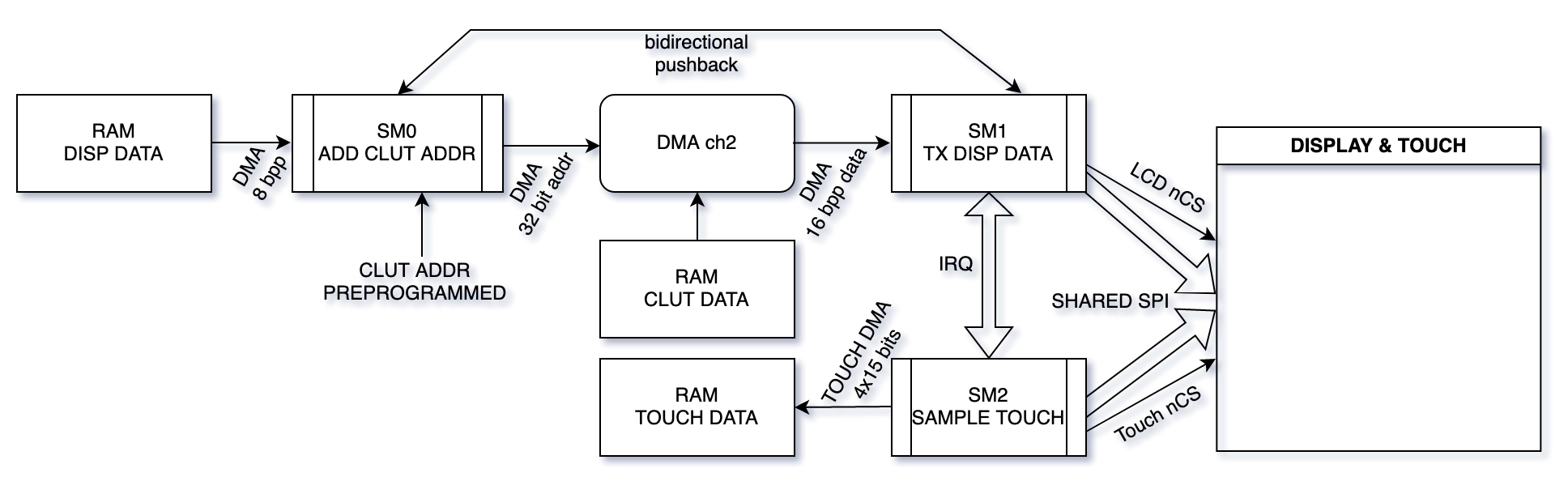
PIO machinery cannot do math efficiently, nor can the DMA units. But PIO can concatenate bit strings. An idea begins to form. Let's say that our CLUT will contain 16-bit RGB565 entries and live in RAM at an address divisible by 512. This means that to get an address of the Nth entry we do not need to add. We can just insert "N" shifted left by 1 into the address, since its lower 9 bits are guaranteed to be zero. This we CAN do in PIO. So SM0 will input pixel data, 8 bits at a time. One of its registers will be pre-programmed with the address of the CLUT, right shifted by 9. It will shift that into the ISR, shift in the pixel value, and shift in a single zero bit. Now it can output this 32-bit value, which is an address, in RAM, of the CLUT entry with the actual RGB565 colour of this pixel.
Cool, but we cannot feed a RAM address to our display - it has no idea what our RAM contains. We can, however use one DMA channel to program another... Yes, we'll DMA out every output from SM0 into the "read address" register of another DMA channel. That channel will be programmed to transfer a single 16-bit value from there to SM1's input. Thus it'll copy the actual RGB565 value to SM1's input. SM1 then simply sends it, as it did for 16bpp mode. We apply the same kind of bidirectional pushback mechanism here as we do for 1/2/4 bpp mode, and the touch sampling works the same here as in all other cases. It is quite convoluted, but it works! The colour table can be updated any time and takes effect immediately, due to how it is used. And yes, I am using a PIO state machine to ... add. Cool, eh?
With some minor work, this mode can be modified to use RGB666 mode for slightly better colour accuracy, but due to needing to send more bits over the SPI bus (24 bits sent per pixel vs 16 for RGB565), the framerate will suffer by a factor of 33%. This is why I compromised on RGB565 for this mode - it is just not worth it for 2 more bits.
Some more details
DMA chaining woes
While working on this project I ran into an issue wherein things would work well, until the CPU's internal AHBlite bus was very loaded, at which point things would break down and a DMA channel would end up misconfigured somehow. After breaking my head over it for a few days and finding no way in which my code was wrong, I filed bug 321. It turns out that RP2040's DMA chaining, in some cases, may trigger the chained channel before the last write has completed. Seems the chain signal is fired when the last write is issued, not when it is completed. In most cases this would be perfectly fine, since almost certainly nobody depends on cycle-exact DMA chaining, and doing it this way makes the signal appear faster. In my case, when one channel reconfigures another, and then chains to it, it mattered, since sometimes the second channel would get triggered to start before the last configuration word had been written. Luckily, the fix is simple. Besides chaining, one may triger a channel by writing to certain register addresses. I modified my DMA configuration to always trigger using such writes and now the whole thing is rock stable. All-in-all, this driver needs six DMA channels and completely takes over PIO0, as it uses 30/32 of its instruction slots and 3/4 of its state machines.
Why no nPENIRQ
Why not use the nPENIRQ output from the touch controller? The sad part is that the signal is borderline useless. Why? Seemingly it should go low when the display is touched, and stay up when it is not. Two obstacles are in the way of using it as specified. First, it is noisy. While the display is not touched, sometimes the signal will go low for a little, randomly. Secondly, while actually sampling, it goes low as per spec. This means that properly sampling it requires both smoothing and proper timing. It turns out to not be worth it.
SD card access
Whoever designed this board had one more nasty surprise up his sleeve. The SD card is also wired into the same SPI bus. Indeed, the same system I use to share the SPI bus between the display and touch could be used to also give some time to the SD card, but since SD can be a rather high-bandwidth peripheral, I decided that this is not worth it. The board has provisions to wire the SD card to different pins (they call it SDIO mode). I recommend doing that since two high-bandwidth peripheral sharing one SPI bus is a recipe for sadness.
Clock speeds
The touch controller has a 2.5MHz maximum clock speed, while the display supports up to 62.5MHz speed. When you use the provided code, make sure to set your clock divider for SM1 correctly such that the data is not sent faster than 62.5MHz and SM2's not talking faster than 2.5MHz. The screen will accept the data a little over 62.5MHz, but as the spec does not allow it, you get no promises how well it'll work. Ditto for touch. It is not worth it.
Setup & use
The discussion so far has been about the steady-state "running" situation. How do we get there? Lazily. I did not bother using PIO at all - just bit-bang SPI using GPIO until we are ready to enable all of this machinery. As setup is uncommon, I do not at all feel bad about this.
I generally enable interrupt on DMA complete for touch, so that the touch coordinate can be processed, smoothed, etc. This can also be disabled if you prefer to just read the location and get the latest touch point instead.
In case you do not wish to use the entire display, the size for the used area can be set in the source code, only that size will then be drawn from the framebuffer. Page-flipping is easy, just modify the mFb variable, and the next screen refresh will use the new base address. It does not matter when you make the modification as the variable is only read once per frame (by DMA). No tearing will ever happen on such a pageflip. If you wish, you can enable "xfer complete" interrupt on the DMA channel that sends the screen data to get an interrupt when the flipping is completed.
The API provided are dispSetDepth() to set the current depth, dispSetClut() to set one or more colour table entries for 8bpp mode, dispInit() to do one-time display init, and dispOn()/dispOff() for turning the display on and off.
Download: [HERE]. License is BSD 2-clause. I am too lazy (and disgusted) to turn this into some sort of an arduino or a micropython library, but I am sure someone else will. My provided code will build standalone with no dependency on anything. License is BSD-2 clause. Enjoy
Comments...
