Table of Contents
- A LARGE warning!
- PalmOS Architecture (and a bit of history)
- Towards the first unauthorized PalmOS port
- Towards the first pirate PalmOS device
- We need hardware, but developing on hardware is ... hard
- Um, but now we need a kernel...
- So, uh, what about all that pesky ARM code?
- You do not mean...? (pt2)
- A JIT's job is never over
- Is PACE fast enough?
- But, you promised hardware...
- Tales of more PalmOS reverse engineering
- Real hardware: reSpring
- More real hardware
- So where does this leave us?
- Source Code
- Article update history
- Comments...
A LARGE warning!
This is a pre-release article about a pre-release project. I will update both so this is not a static document. Keeping track of changes is your job, if you so choose, all I can promise you is that I'll keep a changelist on the bottom of the article
PalmOS Architecture (and a bit of history)
History
PalmOS before 5.4 kept all data in RAM in databases. They came in two types: record databases (what you'd imagine it to be) and resource databases (similar to MacOS classic resources). Each database had a type and a creator ID, each a 32-bit integer, customarily with each 8-bit piece being an ascii char. Most commonly any application would create databases with their creator ID set to its. Certain types also had meaning, like for example appl was an appliction and panl was a preference panel.
PalmOS started out on Motorola 68k processors and ran on them from first development all the way to version 4.x. For version 5, Palm Inc chose to switch to ARM processors, as they allowed a lot more speed (which is always a plus). But what to do about all the software? Lots of PalmOS apps were written for OS 4.x and compiled for m68k processor. Palm Inc introduced PACE - Palm Application Compatibility Extension. PACE intercepted the OsCall SysAppLaunch (and a number of others) and emulated m68k processor, allowing all the old software to run. When m68k apps called an OsCall, PACE would translate the parameters and call the ARM Native OsCall. This meant that while the app's logic was running in emulation, all OsCalls were native ARM and fast. Combine this with the fact that PalmOS 4.x devices usually ran at 33MHz, and PalmOS 5.x devices usually ran at hundreds, there was almost no slowdown, most old apps compiled for PalmOS 4.x ran at a perfectly good speed. It was even good enough for Palm Inc, since most built-in apps (like calendar and contacts were still m68k apps, not ARM). There was also PalmOS 6.x (Cobalt) but it never really saw the light of day and is beyond the scope of this document.
Palm Inc never documented how to write full Native ARM applications on PalmOS 5.x. It as possible, but not documented. The best official way to get the full speed of the new ARM processors was to use the OsCall PceNativeCall to jump into a small bit of native ARM code that Palm Inc called "ARMlet"s and later "PNOlet"s. Palm said that only the hottest pieces of code should be treated this way, and it was rather hard to call OsCalls from these bits of native ARM code (you had to call back into PACE, which would marshal the parameters for the native API, and then call it. The ways to call the real Native OsCalls were also not documented.
PalmOS 5.x kept a lot of the design of PalmOS 4.x, including the shared heap, lack of protected memory, and lack of proper documented multithreading. A new thing was that PalmOS 5.x supported loadable modules. In fact, every Native ARM application or library in PalmOS 5.x is a module. Each module has a module ID, which is required to be system-unique and exist in the range of 0..1023. This is probably why Palm Inc never documented how to produce full Native applications - they could never allow more than 1024 of them to exist.
PalmOS licensees (sony, handspring, etc) got the sources to the OS and all of this knowledge of course. They were able to customize the OS as needed and then shipped it, but the architecture was always mostly the same. This also aids us a lot.
Modules? Libraries? DALs? Drivers?
The kernel of the OS, memory management, most of the drivers, and low level CPU wrangling is done by the DAL. DAL(Module ID 0) exports about 200 OsCalls, give or take based on the PalmOS version. These are low level things like getting battery state, raw access to screen drawing primitives, module loading and unloading, memory map management, interrupt management, etc. Basically these are functions that no user-facing app would ever need to use. On top of the DAL lives Boot. Boot(Module ID 1) provides a lot of the lower-level user-facing OsCalls. Implemented here are things like the DataManager, MemoryManager, AlarmManager, ExchangeManager, BitmapManager, and WindowManager. Feel free to refer to the PalmOS SDK for details on all of those. On top of Boot lives UI. UI(Module ID 2) provides all of the UI primites to the user. These are things like controls (buttons, sliders, etc), forms, menus, tables, and so on. These three modules together make up the core of PalmOS. You could, in fact, almost boot a ROM containing just these three files.
These first three modules are actually somewhat special, being the core of the OS. They are always loaded, and their exported functions are always accessible via a special shortcut. For modules 0, 1, and 2, you can call an exported function number N by executing these two instructions: LDR R12, [R9, #-4 * (module_ID + 1)]; LDR PC, [R12, #4 * func_no]. This shortcut exists for easy calls to OsCalls by native modules and only works because these modules are always loaded. This is not a general rule, and this will NOT work for any other modules. You might ask if one can also write to these tables of function pointers to replace them. Yes, yes you can and this was often done by what were called "hacks" and also is liberally used by the OS itself (but not via direct writes but via an OsCall: SysPatchEntry).
PalmOS lacks any memory protection, any user code can access hardware. PalmOS actually uses this - things like SD card drivers, and drivers for other peripherals are usually separate modules and not part of the DAL. The Boot module will load all PalmOS resource databases of certain types at boot, allowing them to initialize. An incomplete list of these types is: libs(slot driver), libf(filesystem driver), vdrv(serial port driver), aext(system extension), aexo(OEM extension). These things being separate is actually very convenient, since that means that they can be easily removed/replaced. There are of course corner cases, since PalmOS developers never anticipated this. For example, if NO serial drivers are loaded, the OS will crash as it never expected this. Luckily, this is also easy to work around.
Anytime a module is loaded, the entry point is called with a special code, and the module is free to initialize, set up hardware, etc. When it is unloaded, it gets another code, and can deinitialize. There is another special code modules can get and that is from PACE. If you remember, I said that PACE marshals parameters from m68k apps to OsCalls and back, but PACE cannot possibly know about parameters that a random native library takes, so the marshalling there must be done by the library itself. This special code is used to tell the library to: read parameters from the m68k emulated stack, process them, and put the result unto the emulated m68k registers (PACE exports functions to actually manage the emulated state, so the libraries do not need to know of its insides).
Towards the first unauthorized PalmOS port
So what's so hard?
As I mentioned, none of the native API of PalmOS 5.x was ever documented. There was a small number of people who figured out some parts of it, but nobody really got it all, or even close to it. To start with, because large parts are not useful to an app developer, and thus attracted no interest. This is a problem, however, if one wants to make a new device. So I had to actually do a lot of reverse engineering for this project - a lot of boring reverse engineering of very boring APIs that I still had to implement. Oh, and I needed a kernel, and actual hardware to run on.
ROM formats are hard
To start with, I wrote a tool to split apart and put back together working PalmOS ROM images. The format is rather convoluted, and changed between versions, but after a lot of work the "splitrom" tool can now successfully split a PalmOS ROM from pre-release pre-v.1.0 PalmOS devices all the way to the PalmOS 6.0 cobalt ROMs. The "mkrom" tool can now produce valid PalmOS 5.x images - I never bothered to actually make it produce other versions as I did not need it. At this point I took a detour from the project to collect PalmOS ROMs. I now have one from almost every device and prototype. I'll share them with the world later. I tested this by pulling apart a T|T3 ROM, replacing some files, putting it back together, and reflashing my T|T3. It booted! Cool!
So write a DAL and you're done!
I had no hardware to test on, no kernel to use, and a lot more "maybe"s than I was willing to live with, so it was time for action. The quickest way I could think of to try it was to use a real ARM processor and an existing kernel - linux. Since my desktop uses an x86 processor and not ARM, qemu was used. I wrote a basic rudimentary DAL that simply logged any function called and then crashed on purpose. At boot, it did same as PalmOS's DAL does: load Boot and in a new thread call PalmOSMain OsCall. I then wrote a simple "runner" app that used mmap() to map an area of memory at a particular location backed by "rom.bin" and another by "ram.bin" and tried to boot it. I got some logged messages and a crash, as expected. Cool! I guess the concept could work. So, what is the minimum number of functions my DAL needs to boot? Turns out that most of them! Sad day...
Minimal DAL
It took months, but I got most of the DAL implemented, and it ran inside my "runner" inside qemu. It was a very scary setup. Since it was all a userspace app under Linux, I had to call back out to the "runner" to request things like thread creation, etc. It was a mess. Current rePalm code still supports this mode, but I do not expect to use it much, for a variety of reasons. To start with, Linux kernel lacks some API that PalmOS simply needs, for example ability to disable and re-enable task switching. Yup... PalmOS sometimes asks for preemption to be disabled. Linux lacks that ability. PalmOS also needs ability to remotely pause and resume a thread, without the thread's consent. The pthreads library lacks such ability as well. I hacked together some hacks using ptrace, but it was a mess. Fun story: since my machine is multi-core, and I never set any affinities, this was the first time ever that PalmOS ran on a multi-core device. I did not realize it till much later, but that is kind of cool, no?
Drawing is hard
There was one problem. For some reason, things like drawing line, rectangles, circles, and bitmaps were all part of the DAL. Now, it is not hard to draw a line, but things like "draw a rounded rectangle with foreground color of X and a background color of Y, using drawing mode 'mask' on this canvas" or "draw this compresed 16-bit full-color 144ppi image on this 4-bits-per-pixel 108ppi canvas with dithering, respecting transparency colors, and using 'invert' mode" or even "print string 'Preferences' with background color X, foreground Y, text color Z, dotted-underlined, using this low-density font on this 1.5 density canvas" get convoluted quickly. And yes, the DAL is expected to handle this all. Oh, and none of this was ever documented of course! This was a nightmare. At first I treated all drawing functions as NOPs and just logged the drawn text to know how far my boot has gotten. This allowed me to implement many of the other OsCalls that DAL must provide, but eventually I had to face having to draw. My first approach was to just implement things myself, based on function names and some reverse engineering. This approach failed quickly - the matrix of possibilities was simply too large. There are 8 drawing modes, 3 supported densities, 4 image compression formats, 5 supported color depths, and two font formats. It was not possible to think of everything, especially with no way to be sure I had it right. I am not sure if some of these modes ever got exercised by any software in existence at all, but it did not matter - it had to be pixel exact! What to do?
Theft is a form of flattery, right?
I decided on a stopgap measure. I disassembled the Zire72 DAL. And I copied each of the necessary functions, and all the functions they called, and all of the functions those functions called, and so on. I then cleaned up their direct references to Zire DAL's globals, and to each other, and I stuck it all into a giant "drawing.S" file. It was over 30,000 lines long, and I mostly had no idea how it worked. Or if it worked...
It did! Not right away, of course, but it did. Colors were messed up, artifacts everywhere, but I saw the touchscreen calibration screen after boot! Success, yes? Well, not even remotely. To start with, it turns out that in the interest of optimization, PalmOS's drawing code happily sticks its fingers into the display driver's globals. My display "driver" at this point was just an area of memory backed by an SDL surface. It took a lot of work (throwaway work - the worst kind) to figure out what it was looking for and give it to it. But after a few more weeks, Zire72's DAL's drawing code happily ran under rePalm and I was able to see things drawn correctly. After hooking up rudimentary fake touchscreen support, I was even able to interact with the virtual device and see the home screen. Great, but this was all a waste. I do not own that code and cannot ship it. I also cannot improve it, expand it, fix it, or even claim to entirely understand it. This was not a path forward.
Meticulously-performed imitation is also a form of flattery, no?
The time had come. I rewrote the drawing code. Function by function. Line by line. Assembly statement by assembly statement. I tested it after replacing every function as best as I could. Along the way I gained the understanding of how PalmOS draws, what shortcuts for what common cases there are, etc. This effort took two months, after them, 30,000 lines of uncommented assembly turned into 8,000 lines of C. rePalm finally was once again purely my own code! Along the way I optimized a few things and added support for one-and-a-half density, something that the Zire72 DAL never supported. Of all the parts of this project, this was the hardest to slog through, because at the end of every function decoded, understood, and rewritten, there was no noticeable movement forward - the goal was just to not break anything, and there were always dozens of thousands of lines of code to disasemble, understand, and rewrite in C.
Virtual SD card
For testing it would be convenient to be able to load programs easier into the device than baking them into the ROM. I wrote a custom slot driver that did nothing, but only allowed you to use my custom filesystem. That filesystem used hypercalls to reach code in the "runner" to perform filesystem ops on the host. Basically this created a shared folder between my PC and rePalm. I used this to verify that most software and games worked as expected
Which device ROM are you using?
ANY! I tested pre-production Tungsten T image, I tested LifeDrive image, even Sony TH55 ROM boots! Yes, there were custom per-device and per-OS-version tweaks, but I was able to get them to apply automatically at runtime. For example, determining which OS version is running is easily done by examining the number of exported entrypoints of Boot. And determining if the ROM is a Sony device is easy by looking for SonyDAL module. We then refuse to load it, and fake-export equivalent functions ourselves. Why does the DAL need to know the OS version? Some DAL entrypoints changed between PalmOS 5.0 and PalmOS 5.2, and PalmOS 5.4 or later expect a few extra behaviours out of existing funcs that we need to support.
So you're done, right? It works?
At this point, rePalm sort of worked. It was a window on my desktop that ran REAL UNMODIFIED PalmOS with only a single file in the ROM replaced - the DAL. Time to call it done, and pick a new project, right? Well, not quite. Like I said, Linux was not an ideal kernel for this, and making a slightly-more-open PalmOS simulator was not my goal. I wanted to make a device...
Towards the first pirate PalmOS device
A little bit about normal PalmOS 5.x devices, their CPUs, and the progress since...
In order to understand the difficulties I faced, it is necessary to explain some more about how PalmOS 5.x devices usually worked. PalmOS 5.x targetted ARMv4T or ARMv5 CPUs. They had 4-32MB of flash or ROM to contain the ROM, and 8-128MB or RAM for runtime allocations and data storage. PalmOS 5.4 added NVFS, which I shall for now pretend does not exist (as we all wished we could when NVFS first came out). ARMv4T and ARMv5 CPUs implement two separate instruction sets: ARM and Thumb. ARM instructions are each exactly 4 bytes, and are the original instruction set for ARM CPUs. Thumb was added in v4T as a method of improving code density. It is a set of 2-byte long instructions that implement the most common operations the code might want to do, and by being half the size improve code density. Obviously, you do not get something for nothing. In the CPUs back then, Thumb instructions had one extra pipeline stage, so this caused them to be slower in code with a lot of jumps. Also, as the instructions themselves were simpler, sometimes it took more of them to do the same thing. Thumb instructions, in most cases, also only have access to half as many registers as ARM instructions, further leading to slightly less optimal code. But, in general Thumb code was smaller, and speed was not a factor, so large parts of PalmOS were compiled in Thumb mode. (Sony bucks this trend, having splurged for larger flash chips and compiling the entire OS in ARM mode). Some things could also not at all be done in Thumb, for example, 32x32->64 bit multiply, and some were very suboptimal to do in Thumb (like a lot of the drawing code with a lot of complex bit shifts and addressing). These speed-critical pieces were always compiled in ARM mode in PalmOS. Also all library entry points were always in ARM mode with no other options, so even libraries entirely compiled as Thumb, had small thunks from ARM to Thumb mode on each entrypoint.
How does one actually switch modes between ARM and Thumb in ARMv5? Certain, but not all, instructions that change control flow perform the change. Since all ARM instructions are 4-bytes long and always aligned on a 4-byte boundary, any valid ARM instruction's address has the low two bits cleared. Thumb instructions are 2 bytes long, and thus have the bottom one bit cleared. 32-bit-long Thumb2 instructions are also aligned on a 2-byte boundary. This means that for any instruction in any mode, the lower bit of its address is always clear. ARM used this fact for mode switching. The BX instruction would now look at the bottom bit of the register you're jumping to, and if it was 1, treat the destination as Thumb, else as ARM. Any instruction that loads PC with a word will do the same: POP, LDM, LDR instructions. Arithmetic done on PC in Thumb mode does not change to ARM mode ever (low bit ignored) and arithmetic done on PC in ARM mode is undefined if the lower 2 bits produced are nonzero (CAUTION: this is one of the things that ARMv7 changed: this now has defined behaviour). Also an extra instruction was added for easy calls between modes: BLX. There is a form of it that takes a relative offset encoded in the instruction itself, which basically acts like a BL, but also switches modes to whatever NOT the current mode is. There is also a register mode of it that combines what a BX does with saving the return address. Of course to make sure that returns to Thumb mode work as expected, Thumb instructions that save a return address, namely BL and BLX set the lower bit of LR.
ARMv5 at this point in time is ancient history. ARM architecture is up to v8.x by now, with 64-bit-wide-registers and a completely different instruction set. ARMv7 is still often seen around (v8 can also run in v7 mode) and is actually an almost perfect (but actually not entirely so) superset of ARMv5. So I could basically take a dev board for any ARMv7 chip, which are abundant and cheap, and use that as my base, right? Technically yes, but I did not go this way. To start with, few of these CPUs are documented well, so unless you use linux kernel, you'll never get them up - writing your own kernel and drivers for them is not feasible (I am looking at you, allwinner). "But," you might object, "what about Raspberry Pi, isn't its CPU fully documented?" I considered it, but discarded the idea - RasPi is terribly unstable, and I had no desire to build on such a shaky platform. Launch firefox on your RasPi, open dailymail or some other complex site, and go away, come back in 2 weeks, I guarantee you'll be greeted by a hung screen and a kernel panic on the serial console. If even Linux kernel developers cannot make this thing work stably, I had no desire to try. No thanks. So what then?
ARMv7M
The other option was to use a microcontroller - they are plentiful, documented, cheap, and available. ARM designs and sells a large number of small cores under the Cortex brand. Cortex-M0/M0+/M1 are cores based on the ARMv6M spec - basically they run the same Thumb instruction set that ARMv5 CPUs did, with a few extra instructions to allow them to manage privileged state (MRS/MSR/CPS). Cortex-M23 is their successor, which adds a few extra instructions (DIV/CBZ/CBNZ/MOVW/MOVT/B.W) which makes it a bit less of a pain in the ass, but it still is very much a pain for complex work. Cortex-M3/M4/M7 implement ARMv7M spec, which has a very expanded Thumb2 instruction set. It is the same instruction set that ARM introduced into the ARM cores back in the day with ARMv6T2 architecture CPUs. These instructions are a mix of 2 and 4-byte long pieces and are actually pretty good for complex code, supporting long multiplies, complex control flow, and bitfield operations. They can also address all registers and not just half of them like the Thumb instruction set of yore. Cortex-M33 is the successor to these, adding a few more things we do not currently care about. Optionally, these cores can also include an FPU for hardware floating point support. We also do not care about that. There is only one problem: None of these CPUs support ARM instuctions. They all only run Thumb/Thumb2. This means we can run most of PalmOS's Boot and UI, but many other things will fail. Not acceptable. Well, actually, since every library has to be entered in ARM mode, nothing will run...
My kingdom for an ARM!
It is at this point that I decided to extend PalmOS's module format to support direct entry into Thumb mode and converted my DAL to this now format. I also taught my module loader to understand when an library's entry point points to a simple ARM-to-Thumb thunk, and to resolve this directly. This allowed an almost complete boot without needing ARM. But this was not a solution. Large parts of the OS were still in ARM mode (things like MemMove, MemCmp, division routines), and if the goal was to run an unmodified OS and apps, editing everything everywhere was not an option. Some things we could just patch via SysPatchEntry. This I did to the abovementioned MemMove and MemCmp for speed, providing optimal Thumb2 implementations. Other things I could do nothing about - things like integer division (which ARMv5 has no instruction for) were scattered in almost every library, and could not be patched away as they were not exported. We really did need something that ran ARM instructions.
But what if we try?
What exactly will happen if we try to switch an ARMv7M microcontroller into ARM mode? The manual luckily is very clear on that. It WILL switch, clear the status bit that indicated we're in Thumb mode, and then when it tries to execute the next instruction, it will take a UsageFault since it cannot execute in this mode. The Thumb BLX instruction of the form that always switches modes is undefined in ARMv7M, and if executed, the CPU will take a UsageFault as well, indicating in invalid instruction. This all sounds grim, but this is actually fantastic news! We can catch a UsageFault... If you see where I am going with this, and are appropriately horrified, thanks for paying attention! We'll come back to this story arc later, to give everyone a chance to catch up.
We need hardware, but developing on hardware is ... hard
CortexEmu to the rescue
I thought I could make this all work on a Cortex-M class chip, but I did not want to develop on one - too slow and painful. I also did not find any good emulators for Cortex-M class chips. At this point, I took a two-week-long break from this project to write CortexEmu. It is a fully functional Cortex-M0/M3/M23 emulator that faithfully emulates real Cortex hardware. It has a GDB stub so I can attach GDB to it to debug the running code, It has rudimentary hardware emulated to show a screen, and support an RTC, a console, and a touchscreen. It supports privileged and unprivileged mode, and emulates the memory protection unit (MPU) as well. CortexEmu remains the best way to develop rePalm.
Waaaah! You promised real hardware
Yes, yes, we'll get to that, and a lot more later, but that is still months later in the story, so be patient!
Um, but now we need a kernel...
Need a kernel? Why not Linux?
PalmOS needs a kernel with a particular set of primitives. We already discussed some (but definitely not all) reasons why Linux is a terrible choice. Add to that the fact that Cortex-M3 compatible linux is slow AND huge, it was simply not an option. So, what is?
I ended up writing my own kernel. It is simple, and works well. It will run on any Cortex-M class CPU, supports multithreading with priorities, precise timers, mutexes, semaphores, event groups, mailboxes, and all the primitives PalmOS wants like ability to force-pause threads, and ability to disable task switching. It also takes advantage of the MPU to add some basic safety like stack guards. Also, there is great (& fast) support for thread local storage, which comes in handy later. Why write my own kernel, aren't there enough out there? None of the ones out there really had the primitives I needed and bolting them on would take just as long.
So, uh, what about all that pesky ARM code?
The ARM code still was a problem
PalmOS still would not boot all the way to UI because of the ARM code. But, if you remember, as few paragraphs ago I pointed out that we can trap attempts to get into ARM mode. I wrote a UsageFault handler that did that, and then...I emulated it
You do not mean...?
Oh, but I do. I wrote an ARM emulator that would read each instruction and execute it, until the code exited ARM mode, at which point I'd exit the emulation and resume native execution. The actual details of how this works are interesting since the emulator needs its own stack and cannot run on the stack of the emulated code. There also needs to be a place to stash the emulated registers since we cannot just keep them in the real registers (not enough registers for both). Exiting emulation is also kind of fun since you need to load ALL register and status register as well all at once atomically. Not actually trivial on Cortex-M. Well, in any case, "emu.c" and "emuC.c" have the code - go wild and explore.
But isn't writing an emulator in C kind of slow?
You have no idea! The emulator was slow. I instrumented CortexEmu to count cycles, and came up with an average of 170 cycles of host CPU to emulate a single ARM instruction. Not good enough. Not even remotely. It is well known that emulators written in C are slow. C compilers kind of suck at optimizing emulator code. So what next? Well, I went ahead and rewrote the emulator core in assembly. Actually I did it twice. Once for ARMv7M (Cortex-M3 target) and once for ARMv6M (Cortex-M0 target). The speed improved a lot. Now for the M3 core I was averaging 14 cycles per cycle, and for the M0 it was 19. A very respectable emulator performance if I do say so myself.
So, is it fast enough now?
As mentioned before, on original PalmOS devices, ARM code was generally faster than Thumb, so most of the hottest, tightest, fastest code was written in ARM. For us, ARM is 14x slower than Thumb. So the code that was meant to be fastest is slow. But let us take an inventory of this code and see what it really is. Division routines are part of it. ARMv7M implements division in hardware, but ARMv5 did not (nor does ARMv6M). These routines are a hundred cycles or so in ARM mode. MemMove, MemMSet and MemCmp We spoke about already, and we do not care because we replaced them, but lots of libraries had their own internal copies we cannot replace. My guess is that the compiler prefers to inline its own "memset" and "memcpy" in most cases. That made up a large part of the boot process's ARM code usage. Luckily, all of these functions are the same everywhere...
So, can we pattern-match some of these in the emulator code and execute faster native routines? I did this and boot process did go faster. The average per-instr overhead rose due to matching, but boot time shrank. Cool. But what happens after boot? After boot we meet the real monster... PACE's m68k emulator is written in ARM. 60 kilobytes of what is clearly hand-written assembly with lots of clever tricks. Clever tricks suck when you're stuck emulating them... So this means that every single m68k application (which is most of them) is now running under double emulation. Gross... Oh, also: slow. Something had to be done. I considered rewriting PACE, but that is a poor solution - there are a lot of ARM libraries and I cannot rewrite them all. Plus, in what way can I claim to be running an unmodified OS if I replace every bit of it?
There is one more way to make non-native code fast...
You do not mean...? (pt2)
Just in time: this
PACE contains a lot of hot code that is static. On real devices it lives in ROM and does not change. Most libraries are the same. So, what can we do to make it run faster? Translate it to what we can run natively, of course. Most people would not take on a task of writing a just-in-time translator alone. But that is just because they are wimps :) (Or maybe they reasonably assume that it is a huge time sink with more corner cases than one could shake a stick at)
JITs: how do we start?
Basically the same way we did for the emulator. We create a per-thread translation cache (TC) which will hold our translations. Why per thread? Because this avoids the problem of one thread flushing the cache while another is running in it with no end in sight. The TC will contain translation units (TU) each of which represents some translated code. Each TU contains its original "source" ARM address, and then just valid Thumb2 code. There will also be a hashtable which will map source "ARM" addresses to a bucket where the first TU for that hash value is stored. Each bucket is a linked list, and 4096 buckets are used. This is configurable. A fast & simple hash is used. Tested on a representative sample of addresses it gave good distribution. Now, whenever we take a UsageFault that indicates an attempted entry to ARM mode, we lookup the desired address in the hashtable. If we get a hit, we simply replace the PC in the exception frame with the "code" pointer of the matching TU and return. The CPU proceeds to execute native code quickly. Wonderful! What if we do not get a hit? We then save the state and replace the PC in the exception frame with the address of the translation code (we do not want to translate in kernel mode).
Parlez-vous ARM?
The front end of a JIT basically just needs to ingest ARM instructions and understand them. We'll trap on any we do not understand, and try to translate all those that we do. Here we hit our first snag. Some games use instructions that are not valid. Bejeweled, I am looking at you! The game "Bejeweled" has some ARM code included in it and it likes to return by executing LDMDB R11, {R0-R12, SP, PC}^. Ignoring the fact that R0-R2 and R12 do not need to be saved and they are being inefficient, that is also not a valid instruction to execute in user mode at all. That little caret at the end means "also transfer SPSR to CPSR". That request is invalid in user mode and ARM architecture reference manual is very clear that executing this in user mode will have undefined effects. This explains why Bejeweled did not run under rePalm under QEMU. QEMU correctly refused to execute this insanity. Well, I dragged out a Palm device out of a drawer and tested to see what actually happens if you execute this. Turns out that it is just ignored. Well, I guess my JIT will do that too. My emulator cores had no trouble with this instr since as this instr is undefined, treating it like it has no caret was safe, and thus they never even checked the bit that indicated it.
Luckily for us, ARM only has a few instruction formats. Unluckily for us they are all pretty complex. Luckily, decoding is easy. Almost every ARM instruction is conditional and the top 4 bits determine if it executes at all or does not. Data Processing operations are always 3-operand. Destination reg, Source reg, and "Operand" which is ARM's addressing mode 1. It can be an immediate of certain forms, a register, a register shifted by an immediate, or a register shifted by a register. Say what?! Yup, you can do things like ADD R0, R1, R2, ROR R3. Be scared. Be very scared! Setting flags is optional. Loading/storing bytes or words uses addressing mode 2, which allows a use of a register plus/minus an immediate, or register plus/minus register, or register plus/minus register shifted by an immediate. All of these modes can be index, postindex, or index-with-writeback, so scary things like LDR R0, [R1], R2, LSL #12 can be concocted. Loading/storing halfwords or signed data uses addressing mode 3, which is just like mode 2 except no register shifts are available. This mode is also used for LDRD and STRD instructions that some ARMv5 cores implement (this is part of the optional DSP extension). Addressing mode 4 is used for LDM and STM instructions, which are terrifying in their complexity and number of corner cases. They can load or store any subset of registers to a given base address with pre-or-post increment-or-decrement and optional writeback. They are used for stack ops. And last, but not least, there are branches which are all encoded simply and decode easily. Phew...
2 Thumbs do not make an ARM
Initially the thought was that the translation cannot be all that hard? The instructions look similar, and it shouldn't be all that bad. Then reality hit. Hard. Thumb2 has a lot of restrictions on operands, like for example SP cannot at all be treated like a general register, and LR and PC cannot ever be loaded together. It also lacks anything equalling addressing mode 1's ability to shift a register by a register as a third operand to an ALU operation. It lacks ability to shift a third register by more than 3, like mode 2 can in ARM. I am not even going to talk about LDM and STM! Oh, and then there is the issue of not letting the translated code know it is being translated. This means that it must still think it is running from original place, and if it reads itself, see ARM instructions. This means that we cannot ever leak PC's real value into any executable state. The practical upshot of that is that we can never emit a BL instruction, and whenever PC is read, we must instead produce an immediate value which is equal to what PC would have been, had the actual ARM code run from its actual place in memory. Not fun...
Thumb2's LDM/STM actually lack half the modes that ARM has (modes ID and DA) so we'd have to expand those instructions to a lot more code. Oh, and Thumb has limits on writeback that do not match ARM's (more strict) and also you can never use SP in the register set, nor can you ever store PC this way in Thumb2. At this point it becomes abundantly clear that this will not be an easy instruction in -> instruction out job. We'll need places to store temporary immediates, we'll need to rewrite lots of instructions, and we'll need to do it all without causing side effects. Oh, and it should be fast too!
A JIT's job is never over
LDM and STM, may they burn in hell forever!
How LDM/STM work in ARM
ARM has two multiple-register ops: LDM and STM. Each has a few addressing modes. First is the order: up or down in addresses (that is, does the base register address where to store the lowest-numbered register or highest. Next is whether the base register itself is to be used, or should it be incremented/decremented first. This gives us the four basic modes: IA("increment after"), IB("increment before"), DA("decrement after"), DB("decrement before"). Besides that, it is optional to writeback the updated base address to the base register. There are of course corner cases, like what value gests stored if base register with writeback is stored, or what value the base register will have if loaded, while writeback is also specified. ARM spec explicitly defines some of these cases as having unpredictable consequences.
For stack, ARM uses a full-descending stack. That means that at any point, the SP register points to the last ALREADY USED stack position. So, to pop a value, you load it from [SP], and then increment SP by 4. This would be done using an LDM instruction with an IA addressing mode. To push a value unto the stack, one should first decrement SP by 4, and then store the desired value into [SP]. This corresponds to an STM instruction with an DB addressing mode. IB and DA modes are not used for stack in normal ARM code.
How LDM/STM work in Thumb2
So why did I tell you all this? Well, while designing the Thumb2 instruction set, ARM decided what to support and what not to. This basically meant that uncommon things did not get carried forward. Yup...you see where this is going. Thumb2 does not support IB and DA modes. At all. Not cool. But there is more. Thumb2 forbids using PC or SP registers in the list of registers to be stored for STM. Thumb2 also forbids ever loading SP using LDM, also if an LDM loads PC, it may not also load LR, and if it loads LR, it may not also load PC. There is more yet... PC is not allowed as the base register, and the register list must be at least two registers long. This is a somewhat-complete list of what Thumb2 is missing compared to ARM.
But wait, there is more. Even the instrutions that map nicely from ARM to Thumb2 and comply with all the restrictions of Thubm2 are not that simple to translate. For example, storing PC, is as always hard - we need a spare register to store the expected PC value so we can push it. But, registers are pushed in order, so depending on what register we pick as our temporary reg, it might be out of other relative to others, we might need to split the store into a few stores. But, there is more yet. What if the store was to SP or included SP? We changed SP by pushing our temp reg, so we need to adjust for that. But what if this was a STMDB SP!(aka: PUSH). Then we cannot pre-push a temp register that easily...
But wait, there's more ... pain
There is another complication. LDM/STM is expected to act as an atomic instruction to userspace. It is either aborted or resumable at system level. But in Thumb2 in Cortex-M chips, SP is special since the exception frame gets stored there. This means that SP must always be valid, and any data stored BELOW SP is not guaranteed to ever persist (since an interrupt may happen anytime). Luckily, on ARM it was also discouraged to store data below SP and this was rarely done. There is one common piece of PalmOS code that does this: the code around SysLinkerStub that is used to lazy-load libraries. For other reasons rePalm replaced this code anyways though. In all other cases the JIT will emit a warning if an attempt is made to load/store below SP.
As you see, this is very very very complex. In fact, the complete code to translate LDM/STM ended up being just over four thousand lines long and the worst-case translation can be 60-ish bytes. Luckily this is only for very weird instructions the likes of which I have never seen in real code. "So," you might ask, "how could this be tested if no code uses it?" I actually used a modified version of my uARM emulator to emulate both orignal code and translated code to verify that each destination address is loaded/stored once exactly and with proper vales only, and then made a test program that would generate a lot of random valid LDM/STM instructions. It was then left to run over a few weeks. All bugs were exterminated with extreme prejudice, and I am now satisfied that it works. So here is how the JIT handles it, in general (look in "emuJit.c" for details).
Translating LDM/STM
- Check if the instruction triggers any undefined behaviour, or is otherwise not defined to act in a particular way as per the ARM Architecture Reference Manual. If so, log an error and bail out.
- Check if it can be emitted as a Thumb2 LDM/STM, that is: does it comply with ALL the restrictions Thumb2 imposes, and if so, and also if PC is not being stored, emit a Thumb2 LDM/STM
- Check if it can be emitted as a LDR/STR/LDRD/STRD while complying with Thumb2 limits on those. If so, that is emitted.
- A few special fast cases to emit translations for common cases that are not covered by the above (for example ADS liked to use STMIB for storing function parameters to stack)
- For unsupported modes IB and DA, if no writeback is used, they can be rewritten in terms of the supported modes.
- If instruction loads SP, it is impossible to emit a valid translation due to ohw ARMv7-M uses SP. For this one special case, the JIT emits a special undefined instruction and we trap it and emulate it. Luckily no common code uses this ever!
- Finally, the generic slow path is taken:
- Generate a list of registers to be loaded/stored, and at what addresses.
- Calculate writeback if needed.
- If needed, allocate a temporary register or two (we need two if storing PC and SP) and spill their contents to stack
- For all registers left to be loaded/stored, see how many we can load/store at once, and do so. This involves emitting a set of instructions: LDR/STR/LDRD/STRD/LDM/STM until all is done.
- If we had allocated temporary registers, restore them
Slightly less hellish instructions
Addressing mode 1 was hard as well. Basically thanks to those rotate-by-register modes, we need a temporary register to calculate that value, so we can then use it. If the destination register is not used, we can use that as temp storage, since it is about to be overwritten anyways by the result, unless it is also one of the other source operands..or SP...or PC... oh god, this is becoming a mess. Now what if PC is also an operand? We need a temporary register to load the "fake" PC value into before we can operate on it. But once again we have no temporary registers. This got messy very quickly. Feel free to look in "emuJit.c" for details. Long story short: we do our best to not spill things to stack but sometimes we do have to.
The same applies to some complex addressing modes. Thumb2 optimized its instructions for common cases, which makes uncommon cases very hard to translate. Here it is even harder to find temporary registers, because if we push anything, we might need to account for that if our base register is SP. Once again: long story, scary story, see "emuJit.c". Basically: common things get translated efficiently, uncommon ones are not. Special case is PC-based loads. These are used to load constant data. In most cases we inline the constant data into the produced translations for speed.
Conditional instructions
Thumb2 does have ways to make conditional instructions: the IT instruction that makes the next 1-4 instructions conditional. I chose not to use it due to the fact that it also changes how flags get set by 2-byte Thumb instructions and I did not want to special case it. Also sometimes 4 instructions are not enough for a translation. Eg: some STMDA instructions expand to 28 instructions or so. I just emit a branch of opposite polarity (condition) over the translation. This works since these branches are also just 2 bytes long for all possible translation lengths.
Jumps & Calls
This is where it gets interesting. Basically there are two type of jumps/calls. Those whose destinations are known at translation time, and those whose are not. Those whose addresses are known at translation time are pretty simple to handle. We look up the destination address in our TC. If it is found, we literally emit a direct jump to that TU. This makes hot loops fast - no exit from translated code is needed. Indirect or computed jumps are not common, so one would think that they are not that important. This is wrong because there is one type of such jump that happens a lot: function return. We do not, at translation time, know where the return is going to go to. So how do we handle it? Well, if the code directly loads PC, everything will work as expected. Either it will be an ARM address and our UsageFault handler will do its thing or it will be a Thumb address and our CPU will jump to it directly. An optimization exists in case an actual BX LR instruction is seen. We then emit a direct jump to a function that looks up LR in the hash - this saves us the time needed to take an exception and return from it (~60 cycles). Obviously more optimizations are possible, and more will be added, but for now, this is how it is. So what do we do for a jump whose destination is known and we haven't yet translated it? We leave ourselves a marker, namely an instruction we know is undefined, and we follow that up with the target address. This way if the jump is ever actually taken (not all are), we'll take the fault, translate, and then replace that undefined instr and the word following it with an actual jump. Next time that jump will be fast, taking no faults.
Translating a TU
The process is easy: translate instructions until we reach one that we decide is terminal. What is terminal? An unconditional branch is terminal. A call is too (conditional or not). Why? Because someone might return from it, and we'd rather have the return code be in a new TU so we can then find it when the return happens. An unconditional write to PC of any sort is terminal as well. There is a bit of cleverness also for jumps to nearby places. As we translate a TU, we keep track of the last few dozen instructions we translated and where their translations ended up. This way if we see a short jump backwards, we can literally inline a jump to that translation right in there, thus creating a wonderfully fast translation of this small loop. But what about short jumps forward? We remember those as well, and if before we reach our terminal instr we translate an address we remembered a past jump to from this same TU, we'll go back and replace that jump with a short one to here.
And if the TC is full?
You might notice that I said we emit jumps between TUs. "Doesn't this mean," you might ask, "that you cannot just delete a single TU?" This is correct. Turns out that keeping track of which TUs are used a lot and which are not is too much work, and the benefits of inter-TU jumps are too big to ignore. So what do we do when the TC is full? We flush it - literally throw it all away. This also helps make sure that old translations that are no longer needed eventually do get tossed. Each thread's TC grows up to a maximum size. Some threads never run a lot of ARM and end up with small TCs. The TC of the main UI thread will basically always grow to the maximum (currently 32KB).
Growing up
After the JIT worked, I rewrote it. The initial version was full of magic values and holes (cases that could happen in legitimate code but would be mistranslated). It also sometimes emitted invalid opcodes that Cortex-M4 would still execute (despite docs saying they were not allowed). The JIT was split into two pieces. The first was the frontend that ingested ARM instructions, maintained the TC, and kept track of various other state. The second was the backend. The backend had a function for each possible ARMv5 addressing mode or instruction format, and given ANY valid ARMv5 instruction, it could produce a sequence of ARMv7M instructions to perform the same task. For common cases the sequence was well optimized, for uncommon ones, it was not. However, the backend handles ANY possible valid ARMv5 request, even insane things like, for example, RSBS PC, SP, PC, ROR SP. No sane person would ever produce this instruction, but the backend will properly translate it. I wrote tests and ran them automatically to verify that all possible inputs are handled, and correctly so. I also optimized the hottest path in the whole system - the emulation of the BLX instruction in thumb. It is now a whopping 50 cycles faster, which noticeably impacted performance. As an extra small optimization, I noticed that oftentimes Thumb code would use a BLX simply to jump to an OsCall (which due to using R12 and R9 cannot be written in Thumb mode). The new BLX handler detects this and skips emulation by calling the requisite OsCall directly.
I then wrote a sub-backend for the EDSP extension (ARMv5E instructions) since some Sony apps use them. The reason for a separate sub-backend is that ARMv7E (Cortex-M4) has instructions we can use to translate EDSP instructions very well, while ARMv7 (Cortex-M3) does not, and requires longer instruction sequences to do the same work. rePalm supports both.
Later, I went back and, despite it being a huge pain, worked out a way to use the IT instruction on Cortex-M3+. This resulted in a huge amount of code refactoring - basically pushing "condition code" to every backend function and expecting it to conditionalize itself however it wishes. This produced a change with an over-4000-line diff but it workes very well and resulted in a noticeable speed icnrease!
The Cortex-M0 backend
Why this is insane
It was quite an endeavor, but I wanted to see if I could make a working Cortex-M0 backend for my JIT. Cortex-M0 executes the ARMv6-m instruction set. This is basically just Thumb-1, with a few minor additions. Why is this scary? In Thumb-1, most instructions only have access to half the registers (r0..r7). Only three instructions have access to high registers: CMP, MOV, and ADD. Almost all Thumb-1 instructions always set flags. There are also no long-multiply instructions in Thumb-1. And, there is no RRX rotation mode at all. The confluence of all these issues makes attempting a one-to-one instruction-to-instruction translation from ARM to Thumb-1 a non-starter.
To make it all work, we'll need some temporary working space: a few registers. It is all doable with three with a lot of work, and comfortable with four. So I decided to use four work registers. We'll also need a register to point to our context (the place where we'll store extra state). And, for speed, we'll want a reg to store the virtual status register. Why do we need one of those? Because almost all of our Thumb-1 instructions clobber flags, whereas the ARM code we're translating expects flags to stick around during long instruction sequences. So our total is: 6. We need 6 registers. They need to be low registers since, as we had discussed, high registers are basically useless in Thumb-1.
The basics
Registers r0 through r3 are temporary work registers for us. The r4 register is where we keep our virtual status register, and r5 points to our context. We use r12 as another temporary. Yes it is a high-reg but sometimes we really just need to store something, so only being able to MOV something in and out of it is enough. So, what's in a context? Well, then state of the virtual r0 through r5 registers, as well as the virtual r12 and the virtual lr register. There, obviously, needs to be a separate context for every thread, since they may each run different ARM code. We allocate one the first time a thread runs ARM (it is actually part of the JIT state, and we copy it if we reallocate the JIT state).
"But," you might say, "if PalmOS's Thumb code expects register values in registers, and our translated ARM code keeps some of them in a weird context structure, how will they work together?" This is actually complex. Before every translation unit, we emit a prologue. It will save the registers from our real registers into the context. At the end of every translation unit, we emit an epilogue that restores registers from the context into the real registers. When we generate jumps between translation units, we jump past these pieces of code, so as long as we are running in the translated code, we take no penalty for saving/restoring contexts. We only need to take that penalty when switching between translated code and real Thumb code. Actually, it turns out that the prologue and epilogue are large enough that emitting then inside every TU is a huge waste of space, so we just keep a copy of each inside a special place in the context, and have each TU just call them as needed. A later speed improvement I added was to have multiple epilogues, based on whether we know that the code is jumping to ARM code, Thumb code, or "not sure which". This allows us to save a few cycles on exiting translated code. Every cycle counts!
Fault dispatching
There is just one more problem: Those BLX instructions in Thumb mode. If you remember, I wrote about how they do not exist in ARMv7-m. They also do not exist in ARMv6-m. So we also need to emulate them. But, unlike ARMv7-m, ARMv6-m has no real fault handling ability. All faults are considered unrecoverable and cause a HardFault to occur. Clearly something had to be done to work around that. This actually led to a rather large side-project, which I published separately: m0FaultDispatch. In short: I found a way to completely and correctly determine the fault cause on the Cortex-M0, and recover as needed from many types of faults, including invalid memory accesses, unaligned memory accesses, and invalid instructions. With this final puzzle piece found, the Cortex-M0 JIT was functional.
Is PACE fast enough?
Those indirect jumps...
Unfortunately, emulation almost always involves a lot of indirect jumps. Basically that is how one does instruction decoding. 68k being a CISC architecture with variable-length instructions means that the decoding stage is complex. PACE's emulator is clearly hand-written in assembly, with some tricks. It is all ARM. It is actualy the same instruction-for-instruction from PalmOS 5.0 to PalmOS 5.4. The surrounding code changed, but the emulator core did not. This is actually good news - means it was good as is. My JIT properly and correctly handles translating PACE, as evidenced by the fact that rePalm works on ARMv7-M. The main problem is that every instruction emulated requires at least one indirect jump (for common instructions), two for medium-comonness ones, and up to three some some rare ones. Due to how my JIT works, each indirect jump that is not a function return requires an exception to be taken (14 cycles in, 12 out), some glue code (~30 cycles), and a hash lookup (~20 cycles). So even in case that the target code has been translated, this adds 70-ish cycles to each indirect jump. This puts a ceiling on the efficiency of the 68k emulator at 1/70th the speed. Not great. PACE usually is about 1/15 the speed of the native code, so that is quite a slowdown. I considered writing better translation just for PACE, but it is quite nontrivial to do fast. Simply put, there isn't a simple fast way to translate something like LDR R0, [R11, R1, LSL #2]; ADD PC, R11, R0. There simply is no way to know where that jump will go, or that even R11 points to a location that is immutable. Sadly that is what PACE's top level dispatch looks like.
A special solution for a special problem
I had already fulfilled my goal of running PalmOS unmodified - PACE does work with my JIT, and the OS is usable and not slow, but I wanted a better solution and decided that PACE is a unique-enough problem to warrant it. The code emulator in PACE has a single entry point, and only calls out to other code in a 10 clear cases: Line1010 (instruction starting with 0xA), Line1111 (instruction starting with 0xF), TRAP0, TRAP8, TRAPF (OsCall), Division By Zero, Illegal instrction, Unimplemented instruction, Trace Bit being set, and hitting a PC value of precisely 0xFFFFFFF0. So what to do? I wrote a tool "patchpace" that will take in a PACE.prc from any PalmOS device, analyze it to find where those handlers are in the binary, and find the main emulator core. It will then replace the core (in place if there is enough space, appended to the binary if not) with code you provide. The handler addresses will be inserted into your code at offsets the header provides, and a jump to your code will be placed where the old emulator core was. The header is very simple (see "patchpace.c") and just includes halfword offsets from the start of the binary to the entry, and to where to insert jumps to each of the abovementioned handlers as BL or BLX instructions). The only param to the emulator is the state. It is structured thusly: first word is free for emulator to use as it pleases, then 8 D-regs, then the 8 A-regs, then PC, and then SR. No further data is allowed (PACE uses data after here). This same state must be passed to all the handlers. TRAPF handler also needs the next word passed to it (OsCall number). Yes, you understand this correctly, this allows you to bring your own 68k emulator to the party. Any 68k emulator will do, it does not need to know anything about PalmOS at all. Pretty sweet!
Any 68k emulator...
So where do we get us a 68k emulator? Well, anywhere? I wrote a simple one in C to test this idea, and it worked well, but really for this sort of thing you want assembly. I took PACE's emulator as a style guide, and did a LOT of work to produce a thumb2 68k emulator. It is much more efficient than PACE ever was. This is included in the "mkrom" folder as "PACE.0003.patch". As stated before, this is entirely optional and not required. But it does improve raw 68k speed by about 8.4x in the typical case.
But, you promised hardware...
Hardware has bugs
I needed a dev board to play with. The STM32F429 discovery board seemed like a good start. It has 8MB of RAM which is enough, 2MB of flash which is good, a display with a touchscreen. Basically it is perfect on paper. Oh, if only I knew how imperfect the reality is. Reading the STM32F429 reference manual it does sound like the perfect chip for this project. And ST does not quite go out of their way to tell you where to find the problems. The errata sheet is damning. Basically if you make the CPU run from external memory, put the stack in external memory, and SDRAM FIFO is on, exceptions will crash the chip (incorrect vector address read). Ok, I can work around that - just turn off the FIFO. Next erratum: Same story but if the FIFO is off, sometimes writes will be ignored and not actually write. Ouchy! Fine! I'll move my stacks to internal RAM. It is quite a rearchitecturing, but OK, fine! Still crashes. No errata about that! What gives? I removed rePalm and created a 20-line repro scenario. This is not in ST's errata sheet, but here is what I found: if PC points to external RAM, and WFI instruction is executed (to wait for interrupts in a low power mode), and then an interrupt happens after more than 60ms, the CPU will take a random interrupt vector instead of the correct one after waking up! Just imagine how long that took to figure out! How many sleepless nights ripping my hair out at random crashes in interrupt handlers that simply could not possibly be executing at that time! I worked around this by not using WFI. Power is obviously wasted this way, but this is ok for development for now, until I design a board with a chip that actually works!
Next issue: RAM adddress. STM32F429 supports two banks of RAM 0 and 1. Bank 0 starts at 0xC0000000 and Bank 1 at 0xD0000000. This is a problem because PalmOS needs both RAM and flash to be below 0x80000000. Well, we're lucky. RAM Bank 0 is remappable to 0x00000000. Sweet.... Until you realize that whoever designed this board hated us! The board only has one RAM chip connected, so logically it is Bank 0. Right? Nope! It is Bank 1, and that one is not remappable. Well, damn! Now we're stuck and this board is unusable to boot PalmOS. The 0x80000000 limit is rather set in stone.
So why the 0x80000000 limit?
PalmOS has two types of memory chunks: movable and nonmovable. This is what an OS without access to an MMU does to avoid too much memory fragmentation. Basically when a movable chunk is not locked, the OS can move it, and one references it using a "handle". One can then lock it to get a pointer, use it, and then unlock when done. So what has this got to do with 0x80000000? PalmOS uses the top bit of a pointer to indicate if it is a handle or an actual pointer. The top bit being set indicates a handle, clear indicates a pointer. So now you see that we cannot really live with RAM and ROM above 0x80000000. But then again, maybe...
Two wrongs do not make a right, but do two nasty hacks?
Given that I've already decided that this board was only for temporary development, why not go further? Handle-vs-pointer disambiguation is only done in a few places. Why not patch them to invert the condition? At least for now. No, not at runtime. I actually disassembled and hand-patched 58 places total. Most were in Boot, where the MemoryManager lives, a few were in UI since the code for text fields likes to find out of a pointer passed to it is a pointer (noneditable) or a handle (editable). There were also a few in PACE since m68k had a SysTrap to detemine the kind of pointer, which PACE implemented internally. Yes, this is not anymore "unmodified PalmOS" but this is only temporary, so I am willing to live with it! But, you might ask, didn't you also say that ROM and RAM both need to be below 0x80000000? If we invert the condition, we need them both above. But flash is at 0x08000000... Oops. Yup, we cannot use flash anymore. I changed the RAM layout again, carving out 2MB at 0xD0600000 to be the fake "ROM" and I copy the flash to it at boot. It works!
Tales of more PalmOS reverse engineering
SD-card Support
Luckily, I had written a slot driver for PalmOS before, so writing an SD card driver was not hard. In fact, I reused some PowerSDHC source code! rePalm supports SD cards now on the STM32F469 dev board. On the STM32F429 board, they are also supported, but since the board lacks a slot, you need to wire them up yourself (CLK -> C12, CMD -> D2, DAT_0 -> C8). Due to how the board is already wired, only one-bit-wide bus will work (DAT_1 and DAT_2 are used for other tthings and cannot be remapped to other pins), so that limits the speed. Also since your wires will be long and floppy, they maximum speed is also limited. This means that on the STM32F429 the speed is about 4Mbit/sec. On the STM32F469 board the speed is a much more respectable 37MBit/sec. Higher speeds could be reached with DMA, but this is good enough for now. While writing the SD card support for the STM32F4 chips, I found a hardware bug, one that was very hard to debug. The summary is this: SD bus allows the host to stop the clock anytime. So the controller has a function to stop it anytime it is not sending commands or sending/receiving data. Good so far. But that data lines can also be used to signal that the card is busy. Specifically, the DAT_0 line is used for that. The problem is that most cards use the clock line as a reference as to when they can change the state of the DAT lines. This means that if you do something that the card can be busy after, like a write, and then shut down the clock, the card will keep the DAT_0 line low forever, since it is waiting for the clock to tick to raise it. "So," you will ask, "why not enable clock auto-stopping except for this one command?" It does not work since clock auto-stopping cannot be easily flipped on and off. Somehow it confuses the module's internal state machine if it is flipped while the clock is running. So, why stop the clock at all? Minor power savings. Definitely not enough to warrant this mess, so I just disabled the auto-stopping function. A week to debug, and a one line fix! The slot driver can be seen in the "slot_driver_stm32" directory.
Serial Port Support
Palm Inc did document how to write a serial port driver for PalmOS 4. There were two types: virtual drivers and serial drivers. The former was for ports that were not hardwired to the external world (like the port connected to the bluetooth chip or the Infra-red port), and the second for ports that were (like the cradle serial port). PalmOS 5 merged the two types into a unified "virtual" type. Sadly this was not documented. It borrowed from both port types in PalmOS 4. I had to reverse engineer the OS for a long time to figure it out. I produced a working idea of how this works on PalmOS 5, and you can see it in "vdrvV5.h" include file. This information is enough to produce a working driver for a serial port, IrDA SIR port, and USB for HotSync purposes.
Actually making the serial port work on the STM32F4 hardwre was a bit hard. The hardware has only a single one-byte buffer. This means that to not lose any received data at high data rates, one needs to use hardware flow control or make the serial port interrupt the highest priority and hope for the best. This was unacceptable for me. I decided to use DMA. This was a fun chance to write my first PalmOS 5 library that can be used by other libraries. I wrote a DMA library for STM32F4-series chips. The code is in the "dma_driver_stm32" directory. With this, one would think that all would be easy. No. DMA needs to know how many bytes you expect to receive. In case of generic UART data receive, we do not know this. So how do we solve this? With cleverness. DMA can interrupt us when half of a transfer is done, and again when it is all done. DMA can be circular (restart from beginning when done). This gets us almost as far as we need to go. Basically as long as data keeps arriving, we'll keep getting one of these interrupts, and then the other in order. In our interrupt handler, we just need to see how far into the buffer we are, and report the bytes since last time we checked as new data. As long as our buffer is big enough that it does not overflow in the time it takes us to handle these interrupts we're all set, right? Not quite. What if we get just one byte? This is less than half a transfer so we'll never get an interrupt at all, and thus will never report this to the clients. This is unacceptable. How? STM32F4 UART has "IDLE detect" mode. This will interrupt us if after a byte has been RXed, four bit times have expired with no further character starting. This is basically just what we need. If we wire this interrupt to our previous handling code for the circular buffer, we'll always be able to receive data as fast as it comes, no matter the sizes. Cool! The Serial driver I produced does this, and can be seen in the "uart_driver_stm32" directory. I was able to successfully Hotsync over it! IrDA is supported too. It works well. See the photo album for a video demo!
Yes, you can try it!
If you want to try, on the STM32F429 discovery board, the "RX" unpopulated 0.1 inch hole is the STM32's transmit (yes i know, weird label for a transmit pin). B7 is STM32's receive pin. If you connect a USB-to-serial adapter there, you can hotsync over serial. If you instead connect an IrDA SIR transciever there, you'll get working IR. I used MiniSIR2 transciever from Novalog, Inc. It is the same one as most Palm devices use.
Vibrate & LED support
Adding vibration and LED support was never documented, since those are hardware features that vendors handle. Luckily, I had reverse engineered this a long time ago, when I was adding vibration support to T|X. Turns out that I almost got it all right back then. A bit more reverse engineering yielded a complete result of the proper API. LED follows the same API as vibrator: one "GetAttributes" function and one "SetAttributes" function. The settable things are the pattern, speed, delay in betweern repetitions, and number of repetitions. The OS uses them as needed and automatically adds "Vibrate" and "LED" settings to "Sounds and Alerts" preferences panel if it notices the hardware is supported. And rePalm now supports both! The code is in "halVibAndLed.c", feel free to peruse it at your leisure.
Networking support (WIP)
False starts
I really wanted to add support for networking to rePalm. There were a few ways I could think of to do that, such that all existing apps would work. One could simply replace Net.lib with one with a similar interface but controlled by me. I could then wire it up to any interface I wanted to, and all would be magical. This is a poor approach. To start with, while large parts of Net.lib are documented, there are many parts that are not. Having to figure them out would be hard, and proving correctness and staying bug-compatible even more so. Then there is the issue with wanting to run an unmodified PalmOS. Replacing random libraries diminishes the ability to claim that. No, this approach would not work. The next possibility was to make a fake serial interface, and tell PalmOS to connect via it, via SLIP or PPP to a fake remote machine. The other end of this serial port could go to a thread that talks to our actual network interface. This can be made to work. There would be overhead of encoding and decoding PPP/SLIP frames, and the UI would be confusing and all wrong. Also, I'd need to find ways to make the config UI. This is also quite a mess. But at least this mess is achievable. But maybe there is a better approach?
The scary way forward
Conceptually, there is a better approach. PalmOS's Net.lib supports pluggable network interfaces (I call it a NetIF driver). You can see a few on all PalmOS devices: PPP, SLIP, Loopback. Some others also have one for WiFi or Cellular. So all I have to do is produce a NetIF driver. Sounds simple enough, no? Just as you'd expect, the answer is a strong, resounding, and unequivocal "no!" Writing NetIF drivers was never documented. And a network interface is a lot harder than a serial port driver (which was the previous plug-in driver interface of PalmOS that I had reverse engineered). Reverse engineering this would be hard.
Those who study history...
I started with some PalmOS 4.x devices and looked at SLIP/PPP/Loopback NetIF drivers. Why? Like I had mentioned earlier, in 68k, the compiler tends to leave function names around in the binary unless turned off. This is a huge help in reverse engineering. Now, do not let this fool you, function names alone are not that much help. You still need to guess structure formats, parameters, etc. Thus despite the fact that Net.lib and NetIF driver interface both changed between PalmOS 4.x and PalmOS 5.x, figuring out how NetIF drivers worked in PalmOS 4.x would still provide some foundational knowledge. It took a few weeks until I thought I had that knowledge. Then I asked myself: "Was there a PalmOS 4.x device with WiFi?" Hm... There was. Alphasmart Dana Wireless had WiFi. Now that I thought I had a grip on the basics of how these NetIF drivers worked, it was time to look at a more complex one since PPP, SLIP, and Loopback are all very simple. Sadly, Alphasmart's developers knew how to turn off the insertion of function names into the binary. Their WiFi driver was still helpful, but it took weeks of massaging to make sense of it. It is approximately at this point that I realized that Net.lib had many versions and I had to look at others. I ended up disassembling each version of Net.lib that existed to see the evolution of the NetIF driver interface and Net.lib itself. Thus I looked at Palm V's version, Palm Vx's, Palm m505's, and Dana's. The most interesting changes were with v9, where support for ARP & DHCP was merged into Net.lib, whereas previously each NetIF driver that needed those, embedded their own logic for them.
On to OS 5's Net.lib
This was all nice and great, but I was not really in this to understand how NetIF drivers worked in PalmOS 4.x. Time had come to move on to reverse-engineering how PalmOS 5.x did it. I grabbed a copy of Net.lib from the T|T3, and started tracing out its functions, matching them up to their PalmOS 4.x equivalents. It took a few more weeks, but I more or less understood how PalmOS 5.x Net.lib worked.
I found a bug!
Along the way I found an actual bug: a use-after-free in arp_close()
Well, that was easy...
Then I started disassembling PalmOS 5.x SLIP/PPP/Loopback NetIF drivers to see how they had changed from PalmOS 4.x. I assumed that nobody really changed their logic, so any changes I see could be hints on changed in the Net.lib and NetIF structure between PalmOS 4.x and PalmOS 5.x. It turned out that not that much had changed. Structures got realigned, a few attribute values got changed, but otherwise it was pretty close. It is at this point that I congratulated myself, and decided to start writing my own NetIF driver to test my understanding.
NOT!
The self-congratulating did not last long. It turned out that in my notes I marked a few things I had thought inconsequential as "to do: look into this later". Well, it appears that they were not inconsequential. For example: the callback from DHCP to the NetIF driver to notify it of DHCP status was NOT purely informative as I had thought, and in fact a large amount of logic has to exist inside it. That logic, in turn, touches the insides of the DhcpState structure, half of which I had not fully understood since I thought it was opaque to the NetIF driver. Damn, well, back to IDA and more reverse engineering. At some point in time here, to understand what various callbacks between Net.lib and the NetIF driver did, I realized that I need to understand DHCP and ARP a lot better than I did. After sinking some hours into reading the DHCP and ARP RFCs, I dove back into the disassembled code. It all sort of made sense. I'll summarize the rest of the story: it took another three weeks to document every structure and function that ARP and DHCP code uses.
More reverse engineering
There was just one more thing left. As the NetIF driver comes up, it is expected to show UI and call back into Net.lib at various times. Different NetIF drivers I disassembled did this in very different ways, so I was not clear as to what was the proper way to do this. At this point I went to my archive of all the PalmOS ROMs, and wrote a tool to find all the files with the type neti(NetIF drivers have this type), skip all that are PPP, SLIP, or Loopback, and copy the rest to a folder, after deduplicating them. I then disassembled them all, producing diagrams and notes about how each brought itself up and down, where UI was shown or hidden, and when each step was taken. While doing this, I saw some (but not much) logging in some of these drivers, so I was able to rename my own names for various values and structs to more proper ones that writers of those NetIF drivers were kind enough to leak in their log statements. I ended up disassembling: Sony's "CFEtherDriver" from the UX50, Hagiwara's WiFi memorystick driver "HNTMSW_neti", Janam's "WLAN NetIF" from the XP30, Sony's "CFEtherDriver" from the TH55, PalmOne's "PxaWiFi" from Tungsten C, PalmOne's "WiFiLib" from the TX, and PalmOne's "WiFiLib" from their WiFi SD card. Phew, that was a lot! Long story short: the reverse engineered NetIF interface is documented in "netIfaceV5.h" and it is enough that I think a working NetIF driver can be written using it.
"You think?" you might ask, "have you not tested it?". Nope, I am still writing my NetIF driver so stay tuned...
1.5 density support
Density basics
PalmOS since version 4.2 has support for multiple screen densities. That is to say that one could have a device with a screen of the same size, but more pixels in it and still see things rendered at the same size, just with more detail. Sony did have high-res screens before Palm, and HandEra did before both of them, but Palm's solution was the first OS-scale one, so that is the one that PalmOS 5 used. The idea is simple. Each Bitmap/Window/Font/etc has a coordinate system associated with it, and all operations use that to decide how to scale things. 160x160 screens were termed 72ppi (no relation to actual points or inches), and the new 320x320 ones were 144ppi (double density). This made life easy - when the proper density image/font/etc was missing, one could pixel-double the low-res one. The reverse worked to. Pen coordinates also had to be adjusted of course since now the developer could request to work in a particular coordinate system, and the whole system API then had to.
How was this implemented? A few coordinate systems are always in play: native (what the display is), standard (UI layout uses this), and active (what the user set using WinSetCordinateSystem). So given three systems, there are at any point in time 6 scaling factors to convert from any to any other. PalmOS 5.0 used just one. This was messy and we'll not talk about this further. Lets just say this solution did not stick. PalmOS 5.2 and later use 4 scaling factors, representing bidirectional transforms between active and native, and native and standard. Why not the third pair? It is used uncommonly enough that doing two transformations is OK. Since floating-point math is slow on ARMv5, fixed point numbers are used. Here there is a difference between PalmOS 5.2 and PalmOS 5.4. The former uses 16-bit fixed point numbers in 10.6 format, the latter uses 32-bit numbers in 16.16 format. I'll let you read up about fixed-point numbers on your own time, but the crux of the matter is that the number of fraction bits limits the precision of the number itself and the math you can do with it. Now, for precise powers of two, one does not need that many bits, so while there were only 72ppi an 144ppi screens, 10.6 was good enough, with scale factors always being 0x20 (x0.5), 0x40 (x1.0), and 0x80 (x2.0) . PalmOS 5.4 added support for one-and-a-half density due to the overabundance of cheap 320x240 displays at the time. This new resolution was specified as 108ppi, or precisely 1.5 times the standard resolution. Technically everything in PalmOS 5.2 will work as is, and if you give PalmOS 5.2 such a screen, it will more or less sort of work. To the right you can see what that looks like. Yes, not pretty. But it does not crash, and things sort of work as you'd expect. So why does it look like crap? Well, that scaling thing. Let's see what scale factors we might need now. First of all, PalmOS will not ever scale between 108 and 144ppi for bitmaps or fonts, so those scale factors are not necessary (rePalm will in one special case: to draw 144ppi bitmaps on 108ppi screen, when no 72ppi or 108ppi bitmap is available). So the only new scale factors introduced are between standard and 1.5 densities. From standard to 108ppi the scale factor is 1.5, which is representable as 0x60 in 10.6 fixed point format. So far so good, that is exact and math will work perfectly every time. But from 108ppi to 72ppi the scale factor is 2/3, which is NOT representable exactly in binary (no matter how many bits of precision you have). The simple rule with fixed-point math is that when your numbers are not representable exactly, your rounding errors will accumulate to more than one once the values you operate on are greater than one over your LSB. So for 10.6, the LSB is 1/64, so once we start working with numbers over 64, rounding will have errors of over one. This is a problem, since PalmOS routinely works with numbers over 64 when doing UI. Hell, the screen's standard-density width is 160. Oops... These accumulated rounding errors are what you see in that screenshot. Off by one here, off by one there, they add up to that mess. 108ppi density became officially supported in PalmOS 5.4. So what did they do to make it work? Switch to 16.16 format. The LSB there is 1/65536, so math on numbers up to 65536 will round correctly. This is good enough since all of PalmOS UI uses 16-bit numbers for coordinates.
How does it all fall apart?
So why am I telling you all this? Well, PalmOS 5.4 has a few other things in it that make it undesirable for rePalm (rePalm can run PalmOS 5.4, but I am not interested in supporting it) due to NVFS, which is mandatory in 5.4. I wanted PalmOS 5.2 to work, but I also wanted 1.5 density support, since 320x240 screens still are quite cheap, and in fact my STM32F427 dev board sports one. We cannot just take Boot.prc from PalmOS 5.4 and move it, since that also brings NVFS. So what to do? I decided to take an inventory of every part of the OS that uses these scaling values. They are hidden inside the "Window" structure, so mostly this was inside Boot. But there are other ways to fuck up. For example in a few places in UI, sequences like this can be seen: BmpGetDensity( WinGetBitmap( WinGetDisplayWindow())). This is clearly a recipe for trouble because code that was never written to see anything other than a 72 or a 144 as a reply is about to see a 108. But, some of that is harmless, if math is not being done with it. It can quite harmful, however, if it is used in math. I disassembled the Boot from a PalmOS 5.4 device (Treo 680) and one from a PalmOS 5.2 device (Tungsten T3). For each place I found in the T3 ROM that looked weird, I checked what the PalmOS 5.4 Boot did. That provided most of the places of worry. I then searched the PalmOS 5.4 ROM for any references to 0x6C as that is 108 in hex, and a very unlikely constant to occur in code naturally for any other reason (luckily). I also looked at every single division to see if coordinate scaling was involved. This produced a complete list of all the places in the ROM that needed help. There were over 150...
How do we fix it?
Patching this many places is doable, but what if tomorrow I decide to use the Boot from another device? No, this was not a good solution. I opted instead to write an OEM extension (a module that the OS will load at boot no matter what) and fix this. But how? If the ROM is read only, and we do not have an MMU to map a page over the areas we want to fix, how to fix them? Well, every such place is logically in a function. And every function is sometimes called. It may be called by a timer, a notification, be a thread, or be a part of what the user does. Luckily PalmOS only expect UI work form the UI thread, so ALL alf them were only called from use-facing functions. Sadly some were buried quite deep. I got started writing replacement functions, basing them on what the Boot from PalmOS 5.4 did. For most functions I wrote full patches (that is my patch entirely replaces the original function in the dispatch table, never calling back to the original). I wrote 73 of those: FntBaseLine, FntCharHeight, FntLineHeight, FntAverageCharWidth, FntDescenderHeight, FntCharWidth, FntWCharWidth, FntCharsWidth, FntWidthToOffset, FntCharsInWidth, FntLineWidth, FntWordWrap, FrmSetTitle, FrmCopyTitle, CtlEraseControl, CtlSetValue, CtlSetGraphics, CtlSetSliderValues, CtlHandleEvent, WinDrawRectangleFrame, WinEraseRectangleFrame, WinInvertRectangleFrame, WinPaintRectangleFrame, WinPaintRoundedRectangleFrame, WinDrawGrayRectangleFrame, WinDrawWindowFrame, WinDrawChar, WinPaintChar, WinDrawChars, WinEraseChars, WinPaintChars, WinInvertChars, WinDrawInvertedChars, WinDrawGrayLine, WinEraseLine, WinDrawLine, WinPaintLine, WinInvertLine, WinFillLine, WinPaintLines, WinGetPixel, WinGetPixelRGB, WinPaintRectangle, WinDrawRectangle, WinEraseRectangle, WinInvertRectangle, WinFillRectangle, WinPaintPixels, WinDisplayToWindowPt, WinWindowToDisplayPt, WinScaleCoord, WinUnscaleCoord, WinScalePoint, WinUnscalePoint, WinScaleRectangle, WinUnscaleRectangle, WinGetWindowFrameRect, WinGetDrawWindowBounds, WinGetBounds, WinSetBounds, WinGetDisplayExtent, WinGetWindowExtent, WinGetClip, WinSetClip, WinClipRectangle, WinDrawBitmap, WinPaintBitmap, WinCopyRectangle, WinPaintTiledBitmap, WinCreateOffscreenWindow, WinSaveBits, WinRestoreBits, WinInitializeWindow. A few things were a bit too messy to replace entirely. An example of that was PrvDrawControl a function that makes up the guts of CtlDrawControl, but is also used in a lot of places like event handling for controls. What to do? Well, I can replace all callers of it: FrmHandleEvent and CtlDrawControl, but that does not help since PrvDrawControl itself has issues and is HUGE and complex. After tracing it very carefully, I realized that it only really cares about density in one special case, when drawing a frame of type 0x4004, in which case it instead sets the coordinate system to native, and draws a frame manually, and then resets the coordinate system. So, what I did is set a special global before calling it if the frame type requested is that special one, and the frame drawing function, the one I had already rewritten (WinDrawRectangleFrame) then sees that flag and instead does this special one thing. The same had to be done for erasing frame type 0x4004, and the same method was employed. The results? It worked!
There was one more complex case left - drawing a window title. It was buried deep inside FrmDrawForm since a title is technically a type of a frame object. To intercept this without rewriting the entire function, before it runs, I converted a title object to a special king of a list object, and saved the original object in my globals. Why a list? FrmDrawForm will call LstDrawList on a list object, and will not peek inside. I then intercept LstDrawList, check for our magic pointer, if so, draw the title, else let the original LstDrawList function run. On the way out of FrmDrawForm, this is all undone. For form title setting functions, I just replaced them since they redraw the title manually, and I already had written a title drawing function. There was one small thing left: the little (i) icon on forms that have help associated with them. It looked bad when tapped. My title drawing function drew it perfectly, but the tap responce was handled by FrmHandleEvent - another behemoth I did not want to replace. I looked at it, and saw that the handling of the user taps on the help (i) icon was pretty early on. So, I duplicated that logic (and some that preceded it) in my patch for FrmHandleEvent and did not let the original function get that event. It worked perfectly! So thus we have four more partial patches: LstDrawList, FrmDrawForm, FrmHandleEvent, and CtlDrawControl.
And now, for some polish
Still one thing was left to do: proper support for 1.5 density feature set as defined by the SDK. So: I modified the DAL to allow me to patch functions that do not exist in the current OS version at all, since some new ones were added after 5.2 to make this feature set work: WinGetScalingMode and WinSetScalingMode. Then I modified PACE's 68k dispatch handler for sysTrapHighDensityDispatch to handle the new 68K trap selectors HDSelectorWinSetScalingMode and HDSelectorWinGetScalingMode, letting the rest of the old ones be handled by PACE as they were. I also got a hold of 108ppi fonts, and wrote some code to replace the system fonts with them, and I got a hold of 108ppi system images (like the alert icons) and made my extension put them in the right places.
The result? The system looks pretty good! There are still things left to patch, technically, and "main.c" in the "Fix1.5DD" folder has a comment listing them, but they are all minor and the system looks great as is. The "Fix1.5DD" extension is part of the source code that I am releasing with rePalm, and you can see the comparison "after" screenshot just above to the right. It is about 4000 lines of code, in 77 patches and a bit of glue and install logic.
Dynamic Input Area/Pen Input Manager Services support
DIA/PINS basics
PalmOS initially supported square screens. A few OEMS (Handera, Sony) did produce non-square screens, but this was not standard. Sony made quite a headway with their 320x480 Sony Clie devices. But their API was sony-only and was not adopted by others. When PalmOS 5.2 added support for non-square screens, Palm made an API that they called PINS (or alternatively DIA or AIA). It was not as good as Sony's API but it was official, and thus everyone migrated to it. Later sony devices were forced to support it too. Why was it worse? Sony's API was simple: collapse dynamic input area, or bring it back. Enable or disable the button to do so. Easy. Palm's API tries to be smart, with things like per-form policies, and a whole lot of mess. It also has the simple things: put area down or up, or enable or disable the button. But all those settings get randomly mutated/erased anytime a new form comes onscreen, which makes it a huge pain! Well, in any case. That is the public API. How does it all work? In PalmOS 5.4, this is all part of the OS proper, and integrated into Boot.
How it works pre-garnet
But, as I had said, I was tergetting PalmOS 5.2. There, it was not a part of the OS, it was an extension. The DAL presents to the system a raw screen of whatever the actual resolution is (commonly 320x480) and the extension hides the bottom area from the apps and draws the dynamic input area on it. This requires some interception of some OS calls, like FrmDrawForm (to apply the new policy), FrmSetActiveForm (to apply policy to re-activated already drawn forms), SysHandleEvent (to handle events in the dynamic input area), and UIReset (to reset to defaults the settings on app switching). There are also some things we want to be notified about, like screen color depth change. When that happens, we may need to redraw the input area. That is the gist of it. There are a lot of small but significant specifics though.
The intricacies of writing a DIA implementation
Before embarking on writing my own DIA implementation, I tried all the existing ones to see if they would support resolution other than 320x480. I do not want to write pointles code, afterall. None of them worked well. Even such simple things as 160x240 (direct 2x downscaling) were broken. Screens with different aspect ratios like the common 240x320 and 160x220 were even more broken. Why? I guess nobody ever writes generic code. It is simpler to just hack things up for "now" with no plan for "later". Well, I decided to write a DIA implementation that could support almost any resolution.
When the DIA is collapsed, a status bar is shown. It shows small icons like the home button and menu button, as well as the button to unhide the input area. I tried to make everything as generic as possible. For every screen resolution possible, one can make a skin. A skin is a set of graphics depicting the DIA, as well as some integers describing the areas on it, and how they act (what key codes they send, what they do). The specifics are described in the code and comments and samples (3 skins designed to look similar to sony's UIs). They also define a "notification tray" area. Any app can add icons there. Even normal 68k apps can! I am including an example of this too. The clock you see in the status bar is actually a 68k app caled "NotifGeneral" and its source is provided as part of rePalm's source code! My sample DIA skins currently support 320x480 in double-density, 240x320 in 1.5 density, and 160x220 single density. The cool part? The same codebase supports all of these resolutions despite them having different aspect ratios. NotifGeneral also runs on all of those unmodified. Cool, huh? The source code for the DIA implementation is also published with rePalm, of course!
Audio support
PalmOS Audio basics
Since PalmOS 1.0, there has been support for simple sound via a piezo speaker. That means simple beeps. The official API allows one to: play a MIDI file (one channel, square waves only), play a tone of a given volume and amplitude (in background or in foreground), and stop the tone. In PalmOS 5.0, the low level API that backs this simple sound API is almost the same as the high-level official API. HALSoundPlay is used to start a tone for a given duration. The tone runs in the background, the func itself returns directly and immediately. If another tone had previously been started, it is replaced with the new one. A negative duration value means that the tone will never auto-stop. HALSoundOff stops a currently-playing tone, if there is one. HALPlaySmf plays a MIDI tune. This one is actually optional. If the DAL returns an error, Boot will interpret the MIDI file itself, and make a series of calls to HALSoundPlay. This means that unless you have special hardware that can play MIDI better than simple one-channel square waves, it makes no sense to implement HALPlaySmf in your DAL.
PalmOS sampled sudio support
Around the time PalmOS 5.0 came out, the sampled sound API made an appearance. Technically it does not require PalmOS 5.0, but I am not aware of any Palm OS 4 device that implement this API. There were previous vendor-specific audio APIs in older PalmOS releases, but they were nonstandard and generally depended on custom hardware accelerator chips, since 68k processor is not really fast enough to decode any complex audio formats. The sampled sound API is obviously more complex than the simple sound API, but it is easily explained with the concept of streams. One can create an input or output stream, set volume and pan for it, and get a callback when data is available (input) or needed (output). For output streams, the system is expected to mix them together. That means that more than one audio stream may play at the same time and they should all be heard. Simple sound API should also work concurrently. PalmOS never really required support for more than one input stream, so at least that is nice.
A stream (in or out) has a few immutable properties. The three most important ones are the sample rate, the channel number, and the sample format. The sample rate is basically how many samples per second there are. CD audio uses 44,100 per second, most DVDs use 48,000 per second, and cheap voice recorders use 8,000 (approximately telephone quality). PalmOS support only two channel widths: 1 and 2. These are commonly known as "mono", and "stereo". Sample type is a representation of how each sample is represented in the data stream. PalmOS API documents the following sample types: signed and unsigned 8-bit values, signed 16-bit values of any endianness, signed 32-bit values of any endianness, single-precision floating point values of any endianness. As far as I can tell, the only formats ever supported by actual devices were the 8 and 16-bit ones.
Why audio is hard & how PalmOS makes it easy
Mixing audio is hard. Doing it in good quality is harder, and doing it fast is harder yet. Why? The audio hardware can only output one stream, so you need to mix multiple streams into one. Mixing may involve format conversion, for example if hardware needs signed 16-bit little-endian samples and one of the streams is in float format. Mixing almost certainly involves scaling since each stream has a volume and may have a pan applied. And, hardest of all, mixing may involve resampling. If, for example, the hardware runs at 48,000 samples per second, and a client requested to play a stream with 44,100 samples per second, more samples are needed than are provided - one needs to generate more samples. This is all pretty simple to do, if you have large buffers to work with, but that is also a bad idea, since that adds a lot of latency - the larger your buffer, the more time passes between the app providing audio data and the audio coming out the speaker. In the audio world, you are forced to work with relatively small buffers. Users will also notice if you are late delivering audio samples to the hardware (they'll hear it). This means that you are always on a very tight schedule when dealing with audio.
What do existing PalmOS DALs do to address all this difficulty? Mostly, they shamelessly cut corners. All existing DALs have a very bad resampler - it simply duplicates samples as needed to upsample (convert audio to a higher sampling rates), and drops samples as needed to downsample (convert audio to a lower sampling rates). Why is this bad? Well, when resampling between sample rates that are close to each other in this manner, this method will introduce noticeable artifacts. What about format conversions? Well, only supporting four formats is pretty easy - the mixing code was duplicated four times in the DAL, once for each time.
How rePalm does audio mixing
I wanted rePalm to produce good audio quality, and I wanted to support all the formats that PalmOS API claimed were supported. Actually, I ended up supporting even more formats: signed and unsigned 8, 16, and 32-bit integer, as well as single-precision floating-point samples in any endianness. For sample rates, rePalm's mixer supports: 8,000, 11,025, 16,000, 22,050, 24,000, 32,000, 44,100, and 48,000 samples per second. The format the output hardware uses is decided by the hardware driver at runtime in rePalm. Mono and stereo hardware is supported, any sample rate is supported, and any sample format is supported for native hardware output. If you now consider the matrix of all the possible stream input and output formats, sample rates, and channel numbers, you'll realize that it is a very large matrix. Clearly the PalmOS approach of duplicating the code 4 times will not work, since we'd have to duplicate it hundreds or thousands of times. The alternative approach of using generic code that switches based on the types is too slow (the switching logic simply wastes too many cycles per sample). No simple solutions here. But before we even get to resampling and mixing, we need to work out how to deal with buffering.
The initial approach involved each channel having a single circular buffer that the client would write and the mixer would read. This turned out to be too difficult to manage in assembly. Why in assembly? We'll get to that soon. The final approach I settled on was actually simpler to manage. Each stream has a few buffers (buffer depth is currently defined to be four), and after any buffer is 100% filled, it is sent to the mixer. If there are no free buffers, the client blocks (as PalmOS expects). If the mixer has no buffers for a stream, the stream does not play, as PalmOS API specifies. This setup is easy to manage from both sides, since the mixer now never has to deal with partially-filled buffers or sorting out the circular-buffer wraparound criteria. A semaphore is used to block the client conveniently when there are no buffers to fill. "But," you might ask, "what if the client does not give a full buffer's worth of data?" Well, we do not care. Eventually if the client wants the audio to play, they'll have to give us more samples. And in any case, remember how above we discussed that we have to use small buffers? Any useful audio will be big enough to fill at least a few buffers.
One mustn't forget that supporting sampled sound API does not absolve you from having to support simple sound functions. rePalm creates a sound stream for simple sound support, and uses it to play the required tones. They are generated from an interpolated sine wave at request time. To support doing this without any pesky callbacks, the mixer supports special "looped" channels. This means that once the data buffer is filled, it is played repeatedly until stopped. Since at least one complete wave must fit into the buffer, rePalm refuses to play any tones under 20Hz. This is acceptable to me.
How do assembly and audio mix?
The problem of resampling, mixing, and format conversion loomed large over me. The naive approach of taking a sample from each stream, mixing it into the output stream, and then doing the same for the next stream is too slow, due to the constant "switch"ing required based on sample types and sample rates. Resampling is also complex if done in good (or at least passable) quality. So what does rePalm's DAL do? For resampling, a large number of tables are used. For upsampling, a table tells us how to linearly interpolate between input samples to produce output samples. One such carefully-tuned table exists for each pair of frequencies. For downsampling, a table tells us how many samples to average and at what weight. One such table exists for each pair of frequencies. Both of these approaches are strictly better than what PalmOS does. But, if mixing was already hard, now we just made it harder. Let's try to split it into chewable chunks. First, we need an intermediate format - a format we can work with efficiently and quickly, without serious data loss. I picked signed 32-bit fixed point with 8 integer bits and 24 fraction bits. Since no PalmOS device ever produced audio at more than 24-bit resolution, this is acceptable. The flow is conceptually simple: first zero-fill an intermediate buffer. Then, for each stream for which we have buffers of data, mix said buffer(s) into the intermediate buffer, with resampling as needed. Then clip the intermediate buffer's samples, since mixing two loud streams can produce values over the maximum allowed. And, finaly, convert the intermediate buffer into the format hardware supports, and hand it off to the hardware. rePalm does not bother with a stereo intermediate buffer if the audio hardware is mono only. The intermediate buffer is only in stereo if the hardware is! How do we get this much flexibility? Because of how we mix things into it.
The only hard part from above is that "mix buffers into the intermediate buffer with resampling" step. In fact, not only do we need to resample, but we also need to apply volume, pan, and possibly convert from mono to stereo or from stereo to mono. The most optimal approach is to write a custom well-tuned mix function for every possible combination of inputs and outputs. The number of combinations is dizzying. Input has 8 possible rates, 2 possible channel configs, and 12 possible sample types. Output has 8 possible rates and 2 possible channel configs. This means that there is a total of just over 3,000 combinations (8 * 2 * 12 * 8 * 2). I was not going to write 3072 functions by hand. In fact, even auto-generating them at build time (if I were to somehow do that) would bloat rePalm's DAL's code size to megabytes. No, another approach was needed.
I decided that I could reuse some things I learned while I was writing the JIT, and also reuse some of its code. That's right! When you create a stream, a custom mix function is created just for that stream's configuration, and for your hardware's output configuration. This custom assembly code uses all the registers optimally and, in fact, it manages to use no stack at all! The benefit is clear! The mixing code is always optimal since it is custom for your configuration. For example, if the hardware only supports mono output, the mixing code will downmix before upsampling (to do it to fewer samples), but will only downmix after downsampling (once again, so less math is needed). Since there are three major cases: upsampling, downsampling, and no-resampling, there are three paths through the codegen to produce mix functions. Each mix function matches a very simple prototype: int32_t* (*MixInF)(int32_t* dst, const void** srcP, uint32_t maxOutSamples, void* resampleStateP, uint32_t volumeL, uint32_t volumeR, uint32_t numInSamples). It returns the pointer to the first intermediate buffer sample NOT written. srcP is updated to point to the first input audio sample not consumed, maxOutSamples limits how many audio samples may be produced, numInSamples limits how many audio samples may be consumed. Mix functions return when either limit is reached. Resampling logic may have long-lived state, so that is stored in a per-stream data structure (5 words), and passed in as resampleStateP. The actual resample table pointer is encoded in the function itself (for speed), since it will never change. Why? Because the stream's sample rate is constant, and the hardware will not magically grow ability to play at another sample rate at a later time. The stream's volume and pan, however, may be changed anytime, so they are not hardcoded into the function body. They are provided as parameters at mixing time. I actually considered hardcoding them in, and re-generating the mix function anytime the volume or pan changed, but the gain would have been too small to matter, so I decided against it. Instead we simply pre-calculate "left volume" and "right volume" from the user settings of volume" and "pan" and pass them to the mix function.
Having a mix function that nice makes the rest of the mixer easy. Simply: call the mix function for each non-paused stream as long as there are buffers to consume and the output buffer is not full. If we fully consume a buffer, release it to the user. If not, just remember how many samples in there we haven't yet used for later. That is all! So does all this over-complex machinery work? Yes it does! The audio mixer is about 1,500 lines, BUT it can resample and mix streams realtime at under 3 million cycles per stream per second, which is much better than PalmOS did, and with better quality to boot! The code is in "audio.c".
rePalm's audio hw driver architecture
rePalm's audio hardware layer is very simple. For simple sound support, one just provides the funcs for that and the sound layer clals them directly. For sampled audio, the audio init function tells the audio mixer the native channel number and sample rate. What about native sample format? The code provides an inline function to convert a sample from the mixer's intermediate format (8.24 signed integer) to whatever format the hardware needs. Thus, the hardware's native sample format is defined by this inline function. At init time the hw layer provides to the mixer all this info, as well as the size of the hardware audio buffer. This buffer is needed since interrupts have latency and we need the audio hw to always have some audio to play.
On the STM32F429 board, audio output is on pin A5. The audio is generated using a PWM channel, running at 48,000 samples per second, in mono mode. Since the PWM clock runs at 192MHz, if we want to output 48,000 samples per second, the PWM unit will only be able to count to 4000. Yes, indeed, for this board, since it lacks any real audio output hardware, we're stuck with just about 12-bit precision. This is good enough for testing purposes and actually doesn't sound all that bad. The single-ended output directly from the pin of the microcontroller cannot provide much power, but with a small speaker, the sound is clear and sounds great! I will upload an image with audio support soon.
On reSpring, the CPU clock (and thus PWM clock) is at 196.6MHz. Why this weird frequency? Because it is precisely 48,000 x 4096. This allows us to not need to scale audio in a complex fashion, like we do on the STM32F429 board. Just saturating it to 12 bits will work. Also, on reSpring, two pins are used to output audio, in opposite polarity, this gives us twice the voltage swing, producing louder sounds.
Microphone
I did not implement a mixer/resampler for the microphone - PalmOS never supported more than one user of a microphone at a time, so why bother? - no apps will do so. Instead, whichever sampling rate was requested, I pass that to the hardware driver and have it actually run at that sampling rate. As for sample type, same as for audio out, a custom function is generated to convert the sample format from the input (16 bit little-endian mono), to whatever the requested format was. The generated code is pretty tight and works well!
Zodiac support
Tapwave Zodiac primer
Tapwave Zodiac was a rather unusual PalmOS device released in 2003. It was designed for gaming and had some special hardware just for that: landscape screen, an analog stick, a Yamaha Midi chip, and an ATI Imageon W4200 graphics accelerator with dedicated graphics RAM. There was a number of Tapwave-exclusive titles released that used the new hardware well, including some fancy 3D games. Of course this new hardware needed OS support. Tapwave introduced a number of new APIs, and, luckily, documented them quite well. The new API was quite well designed and easy to follow. The documentation was almost perfect. Kudos, Tapwave! Of course, I wanted to support Tapwave games in rePalm.
The reverse engineering
Tapwave's custom API were all exposed via a giant table of function pointers given to all Tapwave-targetting apps, after they pass the signature checks (Tapwave required approvals and app signing). But, of course, somewhere they had to go to some library or hardware. Digging in, it became clear that most of them go to Tapwave Application Layer(TAL). This module is special, in that on the Zodiac, like the DAL, Boot, and UI, the TAL can be accessed directly off of R9 via LDR R12, [R9, #-16]; LDR PC, [R12, #4 * tal_func_no]. But, after spending a lot of time in the TAL, I realized that it was just a wrapper. All the other libraries were too: Tapwave Midi Library and Tapwave Multiplayer Library. All the special sauce was in the DAL. And, boy, was there a lot of special sauce. Normal PalmOS DALs have about 230 entrypoints. Tapwave's has 373!
A lot of tracing through the TAL, and a lot of trawling through the CPU docs got me the names and params to most of the extra exported DAL funcs. I was able to deduce what all but 14 functions do! And as for those 14: I could find no uses of any of them anywhere in the device's software! The actual implementations underneath matter a bit less since I am just reimplementing them. My biggest worries were, of course, the graphics acceleration APIs. Turned out that that part was the easiest!
The "GPU"
Zodiac's graphics accelerator was pretty fancy for a handheld device at the time, but it is also quite basic. It has 8MB of memory built in, and accelerates only 2D operations. Basically, it can: copy rectangles of image data, blend rectangles between layers with constant or parametric alpha blending, do basic bilinear resizing, and draw lines, rectangles, and points. It operates only on 16-bit RGB565LE layers. This was actually quite easy to implement. Of course doing this in software would not be fast, but for the purposes of my proof of concept, it was good enough. A few days of work, and ... it works! A few games ran.
Next step is still in-progress: using the DMA2D unit in the STM32 to accelerate most of the things the ATI chip can do. Except for image resizing, it can do them all in one pass or two! For extra credit, it can also operate in the background like the ATI chip did to the CPU in the Zodiac. But that is for later...
Other Tapwave APIs
Input subsystem in the Zodiac was quite special and required some work. Instead of the usual PalmOS methods of reading keys, touch, etc, they introduced a new "input queue" mechanism that allowed all of these events to be delivered all into one place. I had to reimplement this from nothing but the documented high level API and disassembly. It worked: rePalm now has a working implementation of TwInput and can be used as reference for anyone who also for some reason wants to implement it.
TwMidi was mostly reverse engineered in a week. But I did not write a midi sequencer. I could and shall, but not yet. The API is known and that is as far as I needed to go to return proper error codes to allow the rest of the system to go on.
Real hardware: reSpring
The ultimate Springboard accessory
Back when Handspring first released the Visor, its Springboard Expansion Slot was one of the most revolutionary features. It allowed a few very cool expansion devices, like cellular phones, GPS receivers, barcode readers, expansion card readers, and cameras. Springboard slot is cool because it is a literal direct connection to the CPU's data and address bus. This provides a lot of expansion opportunities. I decided that the first application of rePalm should be a Springboard accessory that will, when pluged in, upgrade a Visor to PalmOS 5. The idea is that reSpring will run rePalm on its CPU, and the Visor will act as the screen, touch, and buttons. I collaborated with George Rudolf Mezzomo on reSpring, with me setting the specs, him doing the schematics and layout, and me doing the software and drivers.
Interfacing with the Visor
To the Visor, the sprinboard module looks like two memory areas (two chip select lines), each a few megabytes large at most. The first must have a valid ROM image for the Visor to find, structured like a PalmOS ROM memory, with a single heap. Usually that heap contains a single application - the driver for this module. The second chip select is usually used to interface to whatever hardware the Springboard unit has. For reSpring I decided to do things differently. There were a few reasons. The main reason was that a NOR flash to store the ROM would take up board space, but also because I really did not want to manage so many different flashable components on the board. There was a third reason too, but we'll need to get back to that in a bit.
The Visor expects to interface with the Springboard by doing memory accesses to it (reads and writes) and the module is expected to basically behave like a synchronous memory device. That means that there is no "i am ready to reply" line, instead you have a fixed number of cycles to reply to any request. When a module is inserted, the Visor configured that number to be six, but it can then be lowered by the module's driver app. Trying to reply to requests coming in with a fixed (and very short) deadline would be a huge CPU load for our ARM CPU. I decided that the easiest way to accomplish this is to actually put a RAM there, and let the Visor access that. But, then, how will we access it, if the Visor can do so anytime? Well, there are special types of RAM that allow this.
Yes, the elusive (and expensive) dual-ported RAM. I decided that reSpring would use a small amount of dual-ported RAM as a malbox between the Visor and rePalm's CPU. This way the Visor could access it anytime, and so could rePalm. The Springboard slot also has two interrupt request lines, one to the Visor, one to the module. These can be used to signal when a message is in the mailbox. There are two problems. The first is that dual-ported RAMs are usually large, mostly due to the large number of pins needed. Since the Visor needs a 16-bit-wide memory in the Springboard slot, our hypotherical dual-ported RAM would need to be 16-bit wide. And then we need address lines, control lines, byte lane select lines, and chip select lines. If we were to use a 4KB memory, for example, we'd need 11 address lines, 16 data lines, 2 byte lane select lines, one chip select line, one output enable line, and one write enable line, PER PORT! Add in at least two power pins, and our hypothetical chip is a 66-pin monstrosity. Since 66-pin packages do not exist, we're all in for a 100-pin part. And 4KB is not even much. Ideally we'd like to fit our entire framebuffer in there to avoid complex piecewise transfers. Sadly, as the great philosopher Jagger once said, "You can't always get what you want." Dual-ported RAMs are very expensive. There are only two companies making them, and they charge a lot. I settled on the 4KB part purely based on cost. Even at this measly 4KB size, this one RAM is by far the most expensive component on the board at $25. Given that the costs of putting in a 64KB part (my preferred size) were beyond my imagination (and beyond my wallet's abilities), I decided to invent a complex messaging protocol and make it work over a 4KB RAM used as a bidirectional mailbox.
But, let us get back to our need for a ROM to hold our driver program. Nowhere in the Sprinboard spec is there actually a requirement for a ROM, just a memory. So what does that mean? We can avoid that extra chip by having the reSpring CPU contain the ROM image inside it, and quickly write it into the dual-ported RAM on powerup. Since the Visor gives the module up to three seconds to produce a valid card header, we have plenty of time to boot up and write the ROM to our RAM. One chip fewer to buy and place on the board is wonderful!
Version 1
I admit: there was a bit of feature creep, but the final hardware design for version 1 ended up being: 8MB of RAM, 128MB of NAND flash, a 192MHz CPU with 2MB of flash for the OS, a microSD card slot, a speaker for audio out, and an amplifier to use the in-Visor microphone for audio in. Audio out will be done the same way as on the STM32F429 board, audio in will be done via the real ADC. The main RAM is on a 32-bit wide bus running at 96MHz (384MB/s bandwidth). The NAND flash is on a QSPI bus at 96MHz (48MB/s bandwidth). The OS will be stored in the internal flash of the STM32F469 CPU. The onboard NAND is just an exploration I would like to do. It will either be an internal SD card, or maybe storage for something like NVFS(but not as unstable), when i've had time to write it.
So, when is this happening? Five version 1 boards were delivered to me in late November 2019!
Bringup of v1
Having hardware in-hand is great. It is greater yet when it work right the vey first time. Great like unicorns, and just as likely. Nope... nothing worked right away. The boards did not want to talk to the debugger at all, and after weeks of torture, i realized some pull ups and downs were missing from the boards. This was not an issue on STM's dev boards since they include these pull ups/downs. Once the CPU started talking to me, it became evident very quickly that it was very very unstable. It is specified to run at 180MHz (yes, this means that normally we are overclocking it by 9.2% to 196.6MHz). On the reSpring boards the CPU would not run with anystability over 140MHz. I checked power supply, and decoupling caps. All seemed to be in place, until... No VCAP1 and VCAP2. The CPU core runs at a lower voltage than 3.3V, so the CPU has an internal regulator. This regulator needs capacitors to stabilize its output in the face of variable consumption by the CPU. That is what VCAP1 and VCAP2 pins are for. Well, the board had no capacitors on VCAP1 and VCAP2. The internal regulator output was swinging wildly (+/- 600mV on a 1.8V supply is a lot of swing!). In fact, it is amazing that the CPU ran at all with such an unstable supply! Well, after another rework under the microscope with two capacitors were added, the board was stable. On to the next problem...
The next issue was SDRAM. The main place the code runs from and data is stored. The interface seemed entirely borked. Any word that was written, the 15th bit would always read as 1, and 0th and 1st bits would always read as a zero. Needless to say, this is not acceptable for a RAM which I hoped to run code from. This was a giant pain to debug, but in the end it there out to be a typo in GPIO config not mapping the two lower bits to be SDRAM DQ0 and DQ1. This left only bit 15 stuck high to resolve. That issue did not replicate on other boards, so that was a local issue to one board. A lot of careful microscoping revealed a gob of solder under the pin left from PCBA, which was shorting to a nearby pin that was high. Lifting the pin, wicking the solder off, and reconnecting the pin to the PCB resolved this issue. SDRAM now worked. Since this SDRAM was quite different than the one on the STM32F429 discovery board, I had to dig up the configs to use for it, and translate between the timings STM uses and the RAM datasheet uses to come up with proper settings. The result was quite fast SDRAM which seems stable. Awesome!
Of course this was not nearly the end of it. I could not access the dual-ported SRAM at all. A quick check with the board layout revelaed that its chip select pin was not at all wired to the STM. Out came the microscope and soldering iron, and a wire was added. Lo and behold, SRAM was accessible. More datasheet reading ensued to configure it properly. While doing that, I noticed that it's power consumption is listed as "low", just 380 mW!!! So not only is this the most expensive chip on the board, it is also the most power hungry! It really needs to go!
I can tell you of more reworks that followed after some in-Visor testing, just to keep all the rework story together. It turned out that the line to interrupt the visor was never connected anywhere, so I wired that up to PA4, so that reSpring could send an IRQ to the visor. Also it turned out that SRAM has a lot of "modes" and it was configured for the wrong one. Three separate pins had to be reworked to switch it from "master" mode into "slave" mode. These modes configure how multiple such SRAMs can be used together. As reSpring only has one, logically it was configured as master. This turns out to have been wrong. Whoops.
Let's stick it into a Visor?
Getting recognized
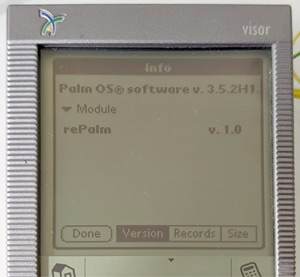
So simple, right? Just stick it into the Visor and be done with it? Reading and re-reading the Handspring Springboard Development Guide provided almost all the info needed, in theory. Practice was different. For some reason, no matter how I formatted the fake ROM in the shared SRAM, the Visor would not recognize it. Finally I gave up on this approach, and wrote a test app to just dump what the Visor sees to screen, in a series of messageboxes. Springboard ROM is always mapped at 0x28000000. I quickly realized the issues. First, the visor Springboard byteswaps all accesses. This is because most of the world is little-endian, while the 68k CPU is big-endian. To allow peripheral designers to not worry, Handspring byteswaps the bus. "But," you might say, "what about non-word accesses?" There are no such accesses. Visor always accesses 16 bits at a time. There are no byte-select lines. For us this is actually kind of cool. As long as we communicate using only 16-bit quantities, no byteswapping in software is needed. There was another issue: the Visor saw every other word that reSpring wrote. This took some investigation, but the result was both hilarious and sad at the same time. Despite all accesses to Springboard being 16-bit-wide, address line 0 is wired to the Springboard connector. Why? Who knows? But it is always low. On reSpring board, Springboard connector's A0 was wired to RAM's A0. But since it is always 0, this means the Visor can only access every other word of RAM - the even addresses. ...sigh... So we do not have 4K of shared RAM. We have 2K... But, now that we know all this, can we get the visor to recognize reSpring as a Springboard module? YES!. The image on the right was taken the first time the reSpring module was recognized by the Visor.
Saving valuable space
Of course, this was only the beginning of the difficulties. Applications run right from the ROM of the module. This is good and bad. For us this is mostly bad. What does this mean? The ROM image we put in the SRAM must remain there, forever. So we need to make it as small as possible. I worked very hard to minimize the size, and got it down to about 684 bytes. Most of my attempts to overlap structures to save space did not work - the Visor code that validates the ROM on the Springboard module is merciless. The actual application is tiny. It implements the simplest possible messaging protocol (one word at a time) to communicate with the STM. It implements no graphics support and no pen support. So what does it do? It downloads a larger piece of code, one word at a time, from the STM. This code is stored in the Visor's RAM and can run from there. It then simply jumps to that code. Why? This allows us to save valuable SRAM space. So we end up with 2K - 684bytes = 1.3K of ram for sending data back and forth. Not much but probably passable.
Communications
So, we have 1.3KB of shared RAM, an interrupt going each way, how do we communicate? I designed two communications protocols: a simple one and a complex one. The simple one is used only to bootstrap the larger code into Visor RAM. It sends a single 16-bit message and gets a single 16-bit response. The messages implemented are pretty basic: a request to reply - just to check comms, a few requests to get information on where in the shared memory the large mailboxes are for the complex protocol, a request for how big the downloaded code is, and the message to download the next word of code. Once the code is downloaded and knows what the locations and sizes of mailboxes are, it uses the complex protocol. How does it differ? A large chunk of data is placed in the mailbox, and then the simple protocol is used to indicate a request and get a response. The mailboxes are unidirectional, and sized very differently. The STM-to-Visor mailbox occupies about 85% of the space, while the mailbox in the other direction is tiny. The reason is obvious - screen data is large.
All requests are always originated from the Visor and get a response from the reSpring module. If the module has something to tell the Visor, it will raise an IRQ, and the visor will send a request for the data. If the visor has nothing to send, it will simply send an empty NOP message. How does the Visor send a request? First, the data is written to the mailbox, then the message type is written to a special SRAM location, and then a special marker indicating that the message is done is written to another SRAM location. An IRQ is then raised to the module. The IRQ handler in the STM looks for this "message valid" marker, and if it is found the message is read and replied to: first the data is written to the mailbox, then message type is written to the shared SRAM location for message type, and then the "this is a reply" marker is written to the marker SRAM location. This whole time, the Visor is simply loop-reading the marker SRAM location waiting for it to change. Is this busy waiting a problem? No. The STM is so fast, and the code to handle the IRQ does so little processing that the replies often come in microseconds.
A careful reading of the Handspring Springboard Development Guide might leave you with a question: "what exactly do you mean when you say 'interrupt to the module'? There are no pins that are there for that!" Indeed. There are, however, two chip-select lines going to the module. The first must address the ROM (SRAM for us). The chip-select line second is free for the module to use. Its base address in Visor's memory map is 0x29000000. We use that as the IRQ to the STM, and simply access 0x29000000 to cause an interrupt to the STM.
Early Visor support
At this point, some basic things could be tested, but they all failed on Visor Deluxe and Visor Solo. In fact, everything crashed shortly after the module was inserted. Why? Actually the reason is obvious - they run PalmOS 3.1, while all other Visors ran PalmOS 3.5. A surprising number of APIs one comes to rely on in PalmOS programming are simply not available on PalmOS 3.1. Such simple things like ErrAlertCustom(), BmpGetBits(), WinPalette(), and WinGetBitmap() simply do not exist. I had to write code to avoid using these in PalmOS 3.1. But some of them are needed. For example, how do I directly copy bits into the display framebuffer if I cannot get a pointer to the framebuffer via BmpGetBits( WinGetBitmap( WinGetDisplayWindow ()))? I attempted to just dig into the structures of windows and bitmaps myself, but it turns out that the display bitmap is not a valid bitmap in PalmOS 3.1 at all. At the end, I realized that PalmOS 3.1 only supported MC68EZ328 and MC68328 processors, and both of them configure the display controller base address in the same register, so I just read it directly. As for palette setting, it is not needed since PalmOS 3.1 does not support color or palettes. Easy enough.
Making it work well
Initial data
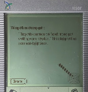
Some data is needed by rePalm before it can properly boot: screen resolution and supported depths, hardware flags (eg: whether screen has brightness or contrast adjustment), and whether the device as an alert LED (yes, you read that right, more on this later). Thus rePalm does not boot until it gets a "continue boot" message that is sent by the code on the Visor once it collects all this info.
Sending display data
The highest-bandwidth data we need to transfer between the Visor and the reSpring module is the display data. For example for a 160x160 scren at 16 bits per pixel at 60 FPS, we'd need to transfer 160x160x16x60 = 23.44Mbps. Not a low data rate at all to attempt on a 33MHz 68k CPU. In fact, I do not think this is even possible. For 4 bits-per-pixel greyscale the numbers look a little better: 160x160x4x60 = 5.86Mbps. But there is a second problem. Each message needs a full round trip. We are limited by Visor's interrupt latency and our general round-trip latency. Sadly that latency is as high as 2-4ms. So we need to minimize the number of packets sent. We'll come back to this later. Initially I just sent the data piecewise and displayed it onscreen. Did it work the first time? Actually, almost. The image to the right shows the results. All it took was a single byteswap to get it to work perfectly!
It was quite slow, however - about 2 frames per second. Looking into it, i realized that the call to MemMove was one of the reasons. I wrote a routine optimized to move the large chunks of data, given that it was not overlapped and always aligned. This improved the refresh rate to about 8 frames per second on the greyscale devices. More improvement was needed. The major issue was the round trip time of copying data, waiting, copying it out, and so on. How do we minimize the number of round trips? Yup - compress the data. I wrote a very very fast lossless image compressor on the STM. It works somewhat like LZ, with a hashtable to find previous occurrences of a data pattern. The compression rations were very very good, and refresh rates went up to 30-40 FPS on the greyscale devices. Color Bejeweled became playable even!
Actually getting the display data was also quite interesting. PalmOS 5 expects the display to just be a framebuffer that may be written to freely. While there are API to draw, one may also just write to the framebuffer. This means that there isn't really a way to get notified when the image onscreen changes. We could send screen data constantly. In fact, this is what I did initially. This depletes the Visor battery at about two percent a minute since the CPU is constantly busy. Clearly this is not the way to go. But how can we get notified when someone draws? The solution is a fun one: we use the MPU. We can protect the framebuffer from writes. Reads are allowed but any write causes an exception. We handle the exception by setting a timer for 1/60 of a second later, and then permit the writes and return. The code that was drawing them resumes, none the wiser. When our timer fires, we re-lock the framebuffer, and request to transfer a screenful of data to Visor. This allows us to not send the same data over and over. Sometimes writes to screen also change nothing, so I later added a second layer where anytime we send a screenful of data, we keep a copy, and next time we're asked to send, we compare, and do nothing if the image is the same. Together with compression, these two techniques bring us to a reasonable power usage and screen refresh rate.
Buttons, pen, brightness, contrast, and battery info
Since the Visor can send data to the reSpring module anytime it wishes, sending button and pen info is easy, just send a message with the data. For transferring data the other way, the design is also simple. If the module requests an IRQ, the visor will send a NOP message, in reply the module will send its request. There are requests for setting display palette, brightness, contrast, or battery info. Visor will perform the requested action, and perhaps reply (eg: for battery info).
Microphone support
The audio amp turned out to be quite miswired on v1 boards, but after some complicated reworks, it was possible to test basic audio recording functionality. It worked! Due to how the reworks worked, the qulity was not stellar, but I could recognize my voice as i said "1 2 3 4 5 6 7" to the voice memo app. But, in reality, amplifying the visor mic is a huge pain - we need a 40dB gain to get anything useful out of the ADC. The analog components of doing this properly and noise-free are just too expensive and numerous, so for v2 it was decided to just populate a digital mic on the board - it is actually cheaper. Plus, no analog is the best amount of analog for a board!
Polish
Serial/IrDA
I support forwarding the Visor's serial port to reSpring. What is this for? HotSync (works) and IR beaming (mostly works). This is actually quite a hard problem to solve. To start with, in order to support PalmOS 3.1, one must use the Old Serial Manager API. I had never used them since PalmOS 4.5 introduced the New Serial Manager and I had almost never written any code for PalmOS before 4.1. The APIs are actually similar, and both quite hostile to what we need. We need to be able to be told when data arrives, without busy-waiting for it. Seemingly there is no API for this. Repeatedly and constantly checking for data works, but wastes battery. Finally I figured out that by using the "receive window" and "wakeup handler" both of which are halfway-explained in the manual, I can get what I need - a callback when data arrives. I also found that, while lightly documented, there is a way to give the Serial manager a larger recieve buffer. This allows us to not drop received data even if we take a few milliseconds to get it out of the buffer. I was able to use all of this to wire up Visor's serial port to a driver in reSpring. Sadly, beaming requires a rather quick response rate, which is hard to reach with our round-trip latency. Beaming works, but not every time. Hotsync does work, even over USB.
Alarm LED
Since rePalm supports alarm LEDs and some Visors have LEDs (Pro, Prism, and Edge), I wanted to wire one up to the other. There are no public API for LED access in the Handspring devices. Some reverse engineering showed that Handspring HAL does have a function to set the LED state: HalLEDCommand(). It does precisely what I want, and can be called simply as TRAP #1; dc.w 0xa014. There is an issue. Earlier versions of Handspring HAL lack this function, and if you attempt to call it, they will crash. "Surely," you might say, "all devices that support the LED implement this function!" Nope... Visor Prism devices sold in the USA do not. The EFIGS version does, as do all later devices. This convenient hardware-independent function was not available to me thus. What to do? Well, there are only three devices that have a LED, and I can detect them. Let's go for direct hardware access then! On the visor edge the LED is on GPIO K4, on the Pro, it is K3, and on the Prism it is C7. We can write this GPUI directly and it works as expected.
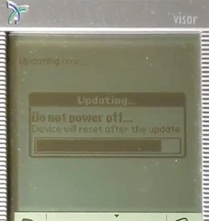
There are two driver modes for LED and vibrator in rePalm - simple and complex. Simple mode has rePalm give the LED/vibrator very simple "turn on now" "turn off now" commands. This is suitable for a directly wired LED/vibrator. In the reSpring case we actually prefer to use the complex driver, where the OS tells us "here is the LED/vibrator pattern, here is how fast to perform it, this many times, with this much time in between. This is suitable for when you have an external controller that drives the LED/vibrator. Here we do have one: the Visor is our external controller. So we simply send these commands to the Visor and our downloaded code performs the proper actions using a simple state machine.
Software update
I wanted reSpring to be able to self-update from SD card. How could this be accomplished? Well, the flash in the STM32 can be written by code running on the STM32, so logically it should not be hard. A few complications exist: to start with, the entire PalmOS is running form flash, including drivers for various hardware pieces. Our comms layer to talk to the Visor is also in there. So to perform the update we need to stop the entire OS and disable all interrupts and drivers. Ok, that is easy enough, but among those drivers are the drivers for the SD card, where our update is. We need that. Easy to solve: copy the update to RAM before starting the update - RAM needs no drivers. But how do we show the progress to the user - our framebuffer is not real, making visor show it requires a lot of code and working interrupts. There was no chance this would work as normal.
I decided that the best way to do this was to have the Visor draw the update UI itself, and just use a single SRAM location to show progress. Writing a single SRAM location is something our update process can do with no issues since the SRAM needs no drivers - it is just memory mapped. The rest was easy: a program to load the update into RAM, send the "update now" message, and then flash the ROM, all the while writing to the proper SRAM location the "percent completed". This required exporting the "send a message" API from the rePalm DAL for applications to use. I did that.
Onboard NAND
You wanted pain? Here's some NAND
The reSpring board has 256MB of NAND flash on a QSPI bus. Why? Because at the time it was designed, I thought it would be cool, and it was quite cheap. NAND is the storage technology underlying most modern storage - your SD cards, your SSD, and the storage in your phone. But, NAND is hard - it has a number of anti-features that make it rather difficult to use for storage. First, NAND may not properly store data - error correction is needed as it may occasionally flip a bit or two. Worse, more bit flips may accumulate over time, to a point where error correction may not be enough, necessitating moving data when such a time approaches. The smallest addressable unit of NAND is a page. That is the size of NAND that may be read or programmed. Programming only flips one bits to zero, not the reverse. The only way to get one bits back is an erase operation. But that operates on a block - a large collection of pages. Because you need error correcting codes, AND bits can only be flipped from one to zero, overwriting data is hard (since the ECC code you use almost certainly will need more ones). There are usually limits to how many times a page may be programmed between erases anyways. There are also usually requirements that pages in a block be programmed in order. And, for extra fun, blocks may go bad (failing to erase or program). In fact a NAND device may ship with bad blocks directly from the factory! Clearly this is not at all what you think of when you imagine block storage. NAND requires careful management to use for storage. Since blocks die due to wear, caused by erasing, you want to evenly wear across the entire device. This may in turn necessitate movinig more data. At the same time while you move data, power may go out so you need to be careful when and what is erased and where it is written. Keeping a consistent idea of what is stored where is hard. This is the job of an FTL - a flash translation layer. An FTL takes the mess that is nand and presents it as a normal block device with a number of sectors which maybe read and written to randomly, with no concern for things like error correction, erase counts, and page partial programming limits.
To write an FTL...
I had written an FTL long ago, so I had some basic idea of the process involved. This was, however, more than a decade ago. It was fun to try to do it again, but better. This time I set out with a few goals. The number one priority was to absolutely never lose any data in face of random power loss since the module may be removed from the Visor randomly at any time. The FTL I produced will never lose any data, no matter when you randomly cut its power. A secondary priority was to minimize the amount of RAM used, since, afterall, reSpring only has 8MB of it!
The pages in the NAND on reSpring are 2176 bytes in size. Of that, 4 are reserved for "bad block marker", 28 are free to use however you wish, with no error correction protection, and the rest is split into 4 equal parts of 536 bytes, which, if you desire, the chip can error-correct (by using the last 16 of those bytes for the ECC code). This means that per page we have 2080 error-corrected bytes and 28 non-error-corrected bytes. Blocks are 64 pages each, and the device has 2048 blocks, of which they promise at least 2008 will be good from the factory. Having the chip do the ECC for us is nice - it has a special hardware unit and can do it much faster then our CPU ever could in software. It will even report to us how many bits were corrected on each read. This information is vital because it tells us about the health of this page and thus informs our decision as to when to relocate the data before it becomes unreadable.
I decided that I would like my FTL to present itself as a block device with 4K blocks. This is the cluster size FAT16 should optimally use on our device, and having larger blocks allows us to have a smaller mapping table (the map from virtual "sector number" to real "page number"). Thus we'd treat two pages together as one always. This means that each of our virtual pages will have 4160 bytes of error-corrected data and 56 bytes of non-erorr corrected data. Since our flash allows writing the same page twice, we'll use the un-error-corrected area ourselves with some handmade error corection to store some data we want to persist. This will be things like how many times this block has been erased, same for prev and next blocks, and the current generation counter to figure out how old the information is. The handmade ECC was trivial: hamming code to correct up to one bit of error, and then replicate the info plus the hamming code three times. This should provide enough protection. Since this only used the un-error-corrected part of the pages, we can then easily write error-correctd-data over this with no issues. Whenever we erase a page, we write this data to it immediately. If we are interrupted, the pages around it have the info we need and we can resume said write after power is back on.
The error-corected data contains the user data (4096 bytes of it) and our service data, such as what vitual sector this data is for, generation counter, info on this and a few neighboring blocks, and some other info. This info allows us to rebuild the mapping table after a power cycle. But clearly reading the entire device each power on is slow and we do not want to do this. We thus support checkpoints. Whenever the device is powered off, or the FTL is unmounted, we write a checkpoint. It contains the mapping data and some other info that allows us to quickly resume operation without scanning the entire device. Of course in case of an unexpected power off we do need to do a scan. For those cases there is an optimization too - a directory at the end of each block tells us what it contains - this allows the scan to read only 1/32nd of the device instead of 100% of it - a 32x speedup!
Read and write requests from PalmOS directly map to the FTL layer's read and write. Except there is a problem - PalmOS only supports block devices with sector sizes of 512 bytes. I wrote a simple translation layer that does read-modify-write as needed to map my 4K sectors to PalmOS's 512-byte sectors, if PalmOS's request did not perfectly align with the FTL's 4K sectors. This is not as scary or as slow as you imagine it, because PalmOS uses FAT16 to format the device. When it does, it asks the device about its preferred block size. We repy with 4K and from then on, PalmOS's FAT driver only writes complete 4K clusters - which align perfectly with out 4K FTL sectors. The runtime memory usage of the FTL is only 128KB - not bad at all, if I do say so myself! I wrote a very torturous set of tests for the FTL and ran it on my computer over a few nights. The test simulated data going bad, power off randomly, etc. The FTL passed. There is actually a lot more to this FTL, and you are free to go look at the source code to see more.
One final WTF
Among all this work, rePalm worked well, mostly. Occasionally it would lose a message from the Visor to the module or vice-versa. I spent a lot of time debugging this and came to a startling realization. The dual-ported SRAM does not actually support simultaneous access to the same address by both ports at once. This is documented in its datasheet as a "helpful feature" but it is anything but. Now, it might be reasonable to not allow two simultaneous writes to the same word, sure. But two reads should work, and a read and a write should work too (with a read returning the old data or the new data, or even a mix of the two). This SRAM instead signals "busy" (which is otherwise never does) to one side. Since it is not supposed to ever be busy, and the Springboard slot does not even have a BUSY pin, these signals were wired nowhere. This is where I found this stuff in the footnote in the manual. It said that switching the chip to SLAVE mode and raising the BUSY pins (which are now inputs) to HIGH will allow simultaneous access. Well, it sort of does. There is no more busy signalling, but sometimes a write will be DROPPED if it is executed concurrently with a read. And a read will sometimes return ZERO if executed concurrently with another read or write, even if the old and new data were both not zero. There seems to be no way around this. Another company's dual-ported SRAM had the same nonsense limitation, leading me to believe that nobody in the industry makes REAL dual-ported SRAMs. This SRAM has something called "semaphores" which can be used to implement actual semaphores that are truly shared by both devices, but otherwise it is not true dual-ported RAM. Damn!
Using these semaphores would require significant rewiring: we'd need a new chip select line going to this chip, and need to invent a new way to interrupt the STM since the second chip select line would be now used to access semaphores. This was beyond my rework abilities, so I just beefed up the protocol to avoid these issues. Now the STM will write each data word that might be concurently read 64 times, and then read it back to verify it was written. The comms protocol was also modified to never ever use zeroes, and thus if a zero is seen, it is clear that a re-read was necessary. With these hacks the communication is stable, but in the next board rev rev I think we'll wire up the semaphores to avoid this nasty hack!
More real hardware
rePalm-MSIO
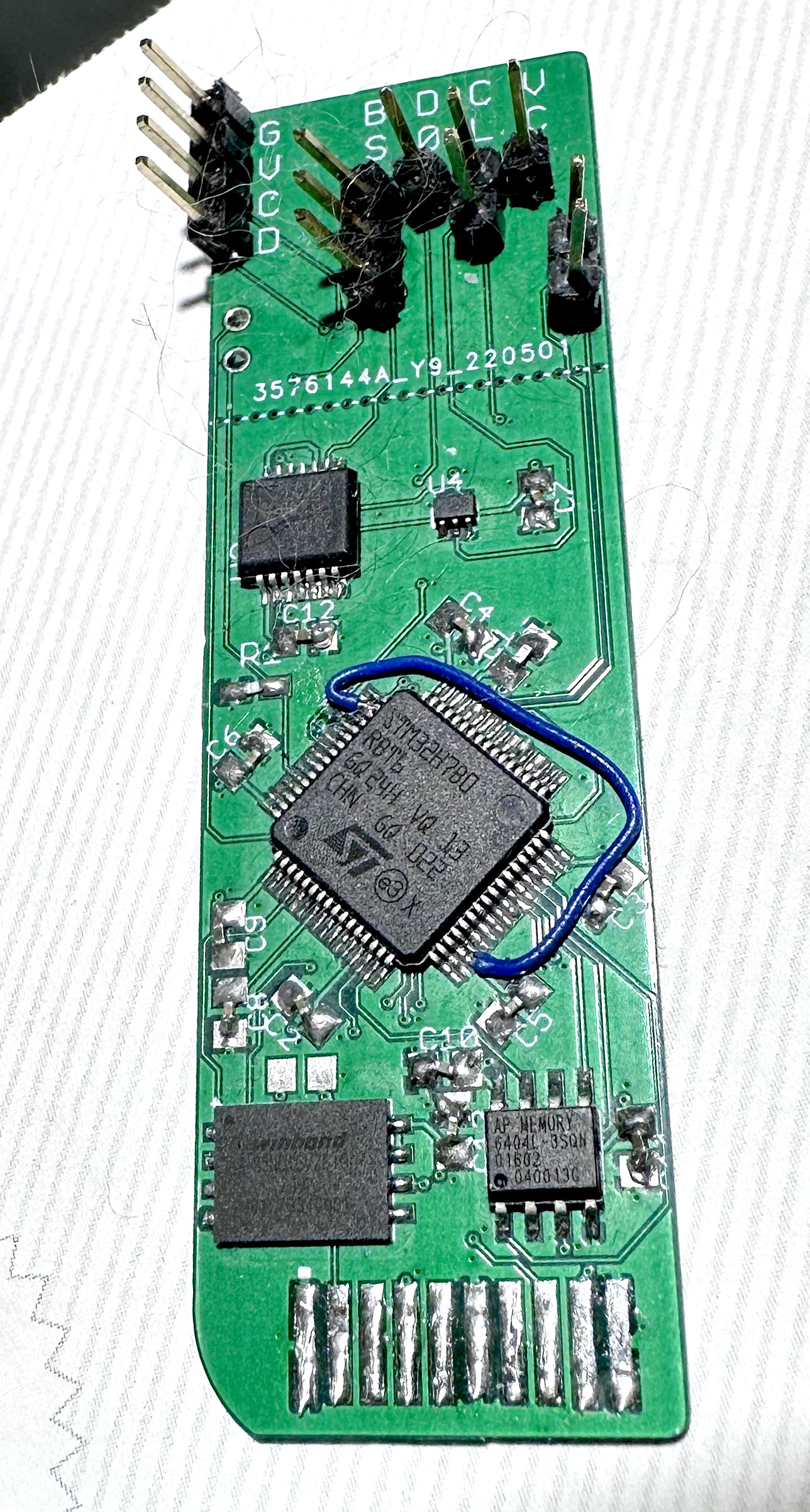
After documenting the Sony MemoryStick protocol, an opportunity presented itself - why not a rePalm version on a MemoryStick? In theory, I could get a microcontroller to act as a MemoryStick device, load a program unto the host Sony PalmOS device, and then take over it, like reSpring did. That was the idea, of course. The space is tight, and timing requirement insane. The fact that the MemoryStick protocol is so much unlike any normal sane bus means that there will be no simple solutions. However, I was determined to make this work.
MCU selection
STM32F429 and an SDRAM chip together would take up too much space to fit inside a MemoryStick slot. Instead, a 64-pin STM32H7 chip is used. It has 1.25MB of internal ram, which is a bit little for PalmOS. Luckily, it supports a rather rare thing: a read/write QSPI interface - perfect for interfacing with QSPI PSRAM chips like APS6404L from APMemory! This allows for 8MB of RAM without taking up a lot of board space or needing a boatload of pins! STM32H7 is also a Cortex-M7, which is quite an improvement from the Cortex-M4 core in the STM32F429. M7 is faster per-cycle, and has a cache! The fact that STM32F429 had no cache was a serious handicapping factor for it when running code from RAM, since the RAM was limited to half the core clock speed. With a small-enough working set, the M7 can operate at full speed from cache! Cool! There is also TCM - some memory near the core that always operates at full speed with no delay or wait-states!
I laid out the board such that it would fit into the MemoryStick slot. It is a 4-layer board (which is apparently very cheap now). This makes routing easier and signal integrity better. With the proper board thickness, there is just enough space for the chips to fit. It all works, inserts, clicks, everything! Pretty amazing, actually. Of course, there were errors, but by the second revision of the board, only one bodge wire was needed, as you can see in the picture. The board is precisely the size of a MemoryStick. There is extra that sticks out, those are the debugging headers and it is break-away. I have one where i did break it away and it is amazing how well it fits inside.
The bugs...
Of course, this being an STM chip, there were bugs. The chip would sometimes lock up entirely when executing from QSPI RAM. When consulted, ST suggested changing the MPU parameters to make the QSPI RAM uncacheable. This is an idiotic suggestion, because even if it worked (spoiler: it does not), it would make that RAM slow beyond any degree of usefulness. In any case, when I tried that, the RAM gets corrupted. I verified with bus traces and presented ot STM. Eventually they admitted that any writes to the QSPI interface that are not sequential and word-sized will cause corruption. Somehow, that info tells me precisely what was the only test they ever ran on this peripheral. Sigh...
Luckily, with the cache on, the dirty cache-line eviction will always sequentially write an integer number of words, so there is hope. Sadly, the chip would work for a while, and then lock up. The lock up was very strange, my debugger would be unable to connect to the core in this state at all, but it could access the debug access port itself. This lead me to believe that it was not the core that locked up but the internal AHB fabric. I was able to confirm this by attaching to another debugger access port (the one on AHB3), where I could look around but have no access to the main AHB busses. STM had no ideas.
Given what I knew about how AHB buses works, guesses on how ST likely designed the arbiters, and how ST likely wired up their QSPI unit to it all, I guessed at the issue, and a workaround the might work. After some prototyping, I can confirm that it does. The performance cost is about 20% (compared to no workaround enabled), but at least no more hangs. Why am I being so cagey about what the workaround is? Well, while denying the issue exists, STM asked for the precise details of my workaround once they heard I had found one. Apparently an actually-important client also hit this issue. I am currently refusing to disclose the workaround until they agree to admit the issue. So far it is a stalemate, which is fine - I am losing no sales over it. Them...?
MSIO low level
The main signal that controls the protocol phases is BS, and it always leads the actual state transition by a cycle, which makes it very hard to use for anything. If only it were not one cycle early, I could use it (and its inverse) as chip-selects and try to use the hardware SPI bus units somehow. After some head-scratching, a solution became evident. Two flip flops will do. Running the BS signal through them will delay it a cycle. Finding a dual-negative-edge-triggered flip-flop turned out to be impossible, so an inverter was thrown into the mix, so that I could use an easily-available SN74LVC74A.
With the BS signal delayed, it could be used as chip select for some SPI units. To make this work, I wired THREE SPI units together. The first edge of BS Triggers a DMA channel that enables three SPI units: one receives the TPC, and the second and third are ready to receive the data that follows. We'll have no time to validate the TPC in the meantime, so we prime the SPI unit to receive it no matter what. This is harmless. This first BS edge also triggers a software interrupt. Assuming not too many delays, we'll arrive into the IRQ after the TPC has already been received and, if the transaction is a write, the data is already on on the way coming in. If we are less lucky, data might have even already been entirely received. Here we can validate the TPC and check its direction. If this is a READ, we need to send the handshaking pattern immediately, so we use one of the SPI units to do that now. While that goes on, we find the data and queue it up for transmission, telling the SPI unit to also send the CRC after it. If this was a WRITE, we had two SPI units receiving the data. One copied the data to RAM, the second to the CRC unit (STM32H7 cannot CRC incoming data if we do not up front know the length). We quickly check the CRC and configure one of the SPI units to send the handshaking pattern to acknowledge the data.
"Now, this all sounds very fragile," an astute observer would say. Yes! Very. It also means that we cannot ever disable interrupts for very long, since there is only a few cycles of leeway between the data being sent to us and a reply being needed to avoid the host timing out. I had to rearchitect rePalm kernel's interrupt handling a little bit, to allow some interrupts to NEVER be disabled, in return for some concessions from those interrupt handlers: they do not make any syscalls or modify any state shared with any other piece of code. So then how do we interface with them? When an MSIO transaction finishes, the data is placed into a shared buffer, and a software interrupt is triggered, which is handled normally by normal code with normal constraints. This can be disabled, prioritized, etc, since it is not time critical anymore. Of course, all the time-critical code must be run from the ITCM (the tightly-coupled instruction memory) to make the deadlines.
When the STM32H7 runs at 320MHz, this works most of the time with newer palm devices, since they run the MSIO interface at 16MHz, giving me some breathing room. Older devices like the S500C are tougher. They run the MSIO bus at 20MHz, and the timings are very tight. Things work well, but if the core is waiting for instruction fetch from QSPI, it will not jump to the interrupt handler till that compltes, causing larger latency. Sometimes this causes an MSIO interrut handler to be late and miss the proper window to ACK some transaction. My host-side driver retries and papers over this. The real solution is a tiny FPGA to offload this from the main MCU. I'm looking into this.
MSIO high level
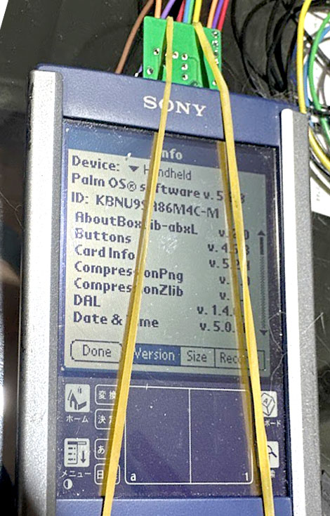
As there exist no MSIO drivers for rePalm, I had to write and provide them. But how would a user get them unto the device? In theory, as far as my reverse-engieering can tell, a MemoryStick may have multiple functions, possibly memory and one or more IO functions. No such stick was observed in the wild, so I set out to create the first. Why not? The logic of how it should work is rather simple - function 0xFF should be memory, and any other unused function number could be for rePalm IO. I picked the function number 0x64. Why pretend to be memory at all? To give the user the driver, of course!
My code does the minimum to pretend to be a read-only MemoryStick with 4MB of storage. As MemorySticks are raw NAND devices, my code pretends to be a perfect one - no bad blocks, no error correction ever needed. The fake medum is "formatted" with FAT12 and contains a rather curious filesystem indeed. To support ALL the sony devices, the driver is needed in a few places. Anything with PalmOS 4.0 or later will show files in /PALM/LAUNCHER to the user, and will auto-launch /PALM/START.prc on insertion. Anything with earlier PalmOS versions will only allow the user to browse /PALM/PROGRAMS/MSFILES. All but the first Sony devices also had another way to auto-launch an executable on stick insertion - a Sony utiliy called "MS AutoRun". It reads a config file at /DEFAULT.ARN and loads the specified program to RAM on insertion. Auto-run is never triggered if the MemoryStick was aleady inserted at device boot, so we cannot rely on it. This is why we need the file to be itself visible and accessible to the user for manual launching. Let's count then, how many copies of the driver app our MemoryStick needs. One in /PALM/LAUNCHER, one in /PALM/PROGRAMS/MSFILES, and one as /PALM/START.prc. Three copies. Now, this will not do! If only FAT12 supported hard links...
But, wait, if the filesystem is read-only, it DOES support hard links! More than one directory entry may reference the same cluster chain. This is only a problem when the file is deleted, which does not happen to a read-only filesystem. The filesystem thus contains a PALM directory in the root, That contains DEFAULT.ARN file, pointing to a cluster with its contents, a PROGRAMS directory, a LAUNCHER directory, and a directory entry with the name START.PRC pointing to the first cluster of our driver. PROGRAMS contains an MSFILES directory, which itself contains another directory entory pointing to the driver, this one with the name DRIVER.PRC. /PALM/LAUNCHER contains the third directory entry pointing to the driver, also named DRIVER.PRC. PalmOS does not do a file system check on read-only media, so no issue is ever hit - it all works.
MSIO performance
Some Sony devices have actual exported MSIO API in their MemoryStick drivers which I was able to reverse engineer (and publish). Some others did not, but Sony published updates that included such API. Usually these updates came with MSIO peripherals like the MemoryStick Bluetooth adapter or the MemoryStick Camera. And some devices never had any official MSIO suport at all. I wanted to support them all, and since I had already reverse engineered how the MemoryStick Host chip (MB86189) worked, I was able to just write my own drivers, talking to it directly. This worked for some devices. Others do not have direct access to the chip, since the DSP controls it. Sony DSP is not documented, the firmware is encrypted, and the key is not known. Here, I was stuck for a while. Eventually I was able to figure out just enough to be able to send and receive raw TPCs via the DSP. This worked well on almost all devices, except the N7xx series devices. Their DSP firmware was the oldest of all (as far as I can tell) and the best bandwidth I was able to coax out of it was 176Kbit/s. Needless to say that this is not quite good enough for live video (basically what rePalm does). It works, but the quality is not great.
As MSIO allows transfers of no more than 512 bytes per transfer, transferring screen image data is complex. The same compression is used here as was used in reSpring. Even then, performance varies based on the device and screen configuration. On low-resolution devices, everything is fast. On high-resolution ones (except N7xx), 35 FPS is reachable in 16bits-per-pixel mode. It is faster on greyscale devices. The lone PalmOS 4 HiRes+ device (NR70V) lags behind at around 20FPS. This is because there is simply so much data to transfer each frame - 300KB.
Other loose ends
Curiously, it seems that Asus licensed the MemoryStick IP from Sony, so the Asus PalmOS devices (s10 and s60 families) also use MemoryStick. I added support for them. For each device, I wired up as much as possible to rePalm. Devices with a LED have it wired to the attention manager, devices with the vibrate motor have that wired up as well. Sound is a bit more complex. Some of these devices had a DSP for MP3 decoding, but the ability to play raw sampled sound is limited, since 68K was unlikely to be able to do it fast enough anyways. There exists a sony API to play 8KHz 4-bits-per-sapme ADPCM. I considered wiring that up to the sound output of rePalm, but did not get around to it. It is likely not worth it as the quality will be atrocious. I did consider the alternative - have rePalm encode its output as MP3, and somehow find a way to feed that to the DSP, but I was stymied in my efforts. In most of the devices, the DSP firmware reads the MP3 file directly from the MemoryStick, bypassing the OS entirely, leading me to believe that I may not find a way to inject MP3 data even if I made it.
Initially, I did the development on STM32H7B0RB. This variant has only 128KB of flash, which is, of course, not enough to contain PalmOS. I used some of the RAM to contain a ROM image, which I loaded over SWD each time. This worked well enough, but was not really fun as it could not be used away from a computer. Luckily, I was able (with a lot of help from an unnamed source) to get some of the STM32H7 chips with 2MB of internal flash. This IS enough to fit PalmOS, so now I have variants that boot directly on insertion. The latest boards also have some onboard NAND flash that acts as a built-in storage device for user using my FTL, mentioned before. The photo album (linked above) has more photos and videos! Here is one. Enjoy!
AximX3
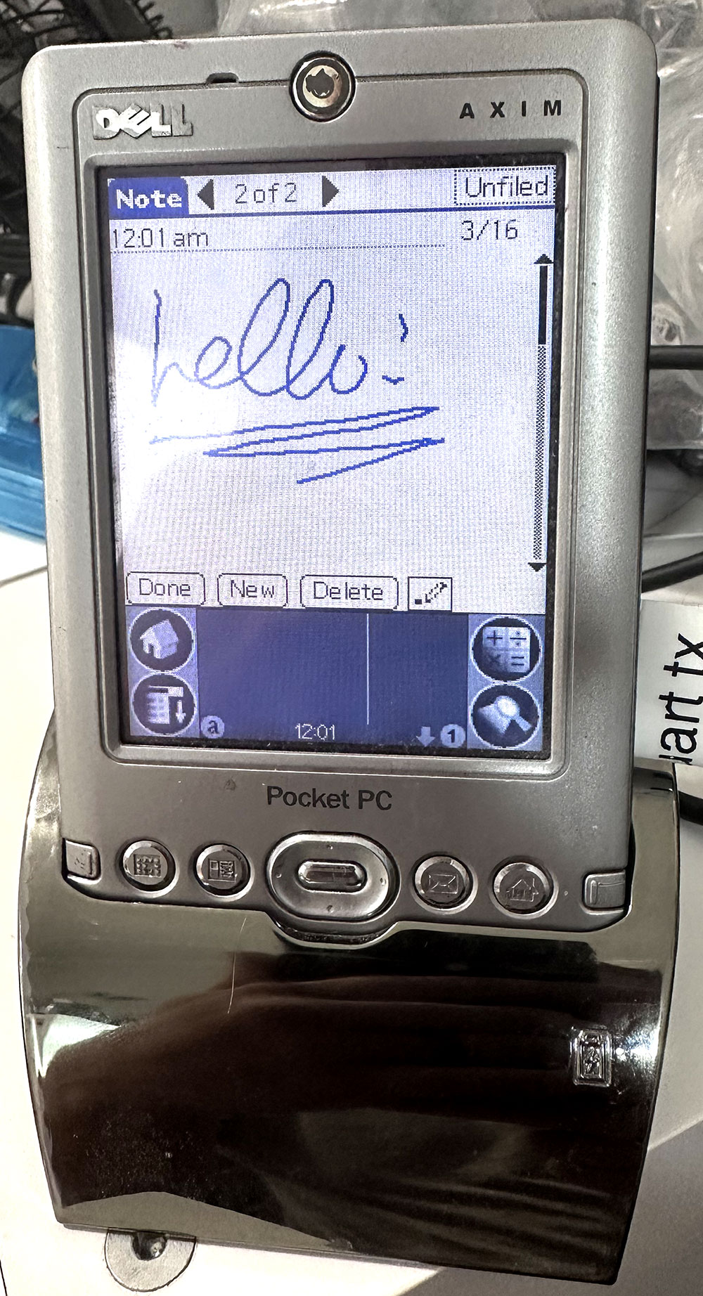
This was a fun target just for shits and giggles. As this runs an ARMv5T CPU, my kernel was forced to adapt to this world. It was not terribly difficult and it works now. Curiously, this device is rather similar internally to the Palm Tungsten T3, so this same rePalm build can run with few modifications on the T|T3 as well.
I put a lot of work into this device. Luckily, a lot of the initial investigation of the hardware was already done as part of my uARM-Palm project. Almost everything works. Audio in and out work, SD card works, infrared works, touch and buttons work, battery reporting works, and the screen works. Missing is only USB and sleep/wake. The first I see no point in, the second is complicated by the built-in bootloader. Initial builds of this used a WinCE loader I wrote to load the ROM into RAM and run from there. Further investigation of the device ROM indicated to me that there is a rather complete bootloader there, capable of flashing the device ROM from the SD card. I decided to exploit that, and with some changes, now rePalm can be flashed to ROM of the device and boot directly. Yes!
How? The stock bootloader has a mode for this. If an image file is placed on the SD card as /P16R_K0.NB0, the card is inserted, jog wheel select and the second app button are held, and the device resetted, it'll flash the image to flash, right after the bootloader. This can be used to flash rePalm, or to reflash the stock image. Depending on the AximX3 version (there are three), the amount of flash and RAM differs. rePalm detects the available RAM and uses it all!
STM32F469 Discovery Board
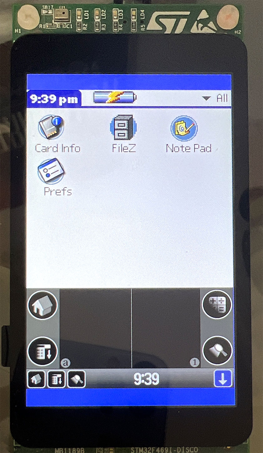
This was a quick little hack to see in real life PalmOS running on a 3x density display. No such device ever shipped. The STM32F469DISCOVERY board has a 480x800 display, of which 480x720 is used as a 3x density display with a dynamic input area. This board has a capacitive touch screen, which makes it ill-suited for PalmOS. Capacitive touch screens are very bad for precise tapping of small elements, since your finger would normally obscure whatever it is that you are trying to tap. This screen being rather large helps a little, but not really all that much. I got this board working well enough to see what it is like, but put little work into it afterwards. Screen, touch, and SD card are the only things supported. It does not help that just like the STM32F429, STM32F469 lacks any cache, making it rather slow when running out of SDRAM.
RP2040
It is possible!
How little RAM/CPU does PalmOS 5 really require? Since rePalm had support (at least in theory) for Cortex-M0, I wanted to try on real hardware, as previously the support was tested on CortexEmu only. There does happen to be one Cortex-M0 chip out there with enough ram - the RP2040 - the chip in the $4 Raspberry Pi Pico. I then sought out a display with a touchscreen that could be easily bought. There were actually not that many options, but this one seemed like a good fit. It turned out, after some investigation, that driving it properly and quickly will not be at all easy. RP2040's special sauce - the PIO - to the rescue! I found a way to do it. I switched the resistors on the screen's board from "SPI" to "SDIO" to enable the SD card, and I wired up the LED to be the alarm LED for PalmOS. Those were the easy things.
As this project depends on some undocumented behaviour in the Cortex-M chips, it was always unknown what would happen in some cases. For example, Cortex-M3 causes a UsageFault when you jump to an address without the bottom bit set, indicating a switch to ARM mode. What would Cortex-M0 do? Turns out - it simply causes a HardFault. m0FaultDispatch to the rescue! It is able to categorize all the causes of a HardFault and wire them to the proper place. I did find one difference from the Cortex-M3. When the Cortex-M3 executes a BX PC instruction, it will execute a jump to the current address plus 4, in ARM mode. This differs from what ARMv5 chips do when you execute that same instruction in Thumb mode. They jump to the current address plus 4, rounded down to the nearest multiple of 4, in ARM mode. This difference my JIT and emulator code alrady handled. But Cortex-M0 does yet a third thing in this case. It actually seems to treat the actual instruction as invaild. PC is not changed, mode is not changed, and a HardFault is taken right on the instruction itself. Curiously, this does not happen if another non-PC register with the low bit clear is used. Well, in any case, I adjusted the JIT and the emulator code to handle this. I also modified CortexEmu to emulate this properly.
Memories
RP2040 lacks any flash, it uses an external Q/D/SPI flash for code and data storage. This is convenient when you have a lot of data. For rePalm this means we can have a ROM as big as the biggest flash chip we can buy. The Pi Pico comes with a 2MB chip, so i targetted that. The RAM situation is much tighter. There is just 264KB of RAM in there. This is not much. The last PalmOS device to have this little RAM ran PalmOS 1.0. But it is worth trying. One of the largest RAM expenditures are graphics. The primary one is the framebuffer. PalmOS assumes that the display has a framebuffer that is directly accessible by the CPU. This means that if I wanted to use the entire 320x240 display in truecolor mode, the framebuffer would occupy 150Kb. Oof! Well, how much IS acceptable?
Some experimentation followed. To boot successfully and to launch the launcher, preferences app, and the digitizer calibration panel successfully, approximately 128KB of dynamic RAM is necessary. The various default databases as well as PACE temporary databases in the storage heap mandate a storage heap of at least 50KB. A 64KB minimum storage heap size is preferred, really, so we do not immediately run out of space at boot. And rePalm's DAL needs at least 15KB of memory for its data structures and about 24KB for the kernel heap where stacks and various other data structures are allocated. Let's add those up. The sum is 231KB. that leaves at most 33KB for the framebuffer. There are a few options. We can use the whole screen at 2 bits per pixel (4 greys). This will need a 18.75KB framebuffer. We can use a square 240x240 screen at 4 bits per pixel, for a 28.125KB framebuffer. We can also use the standard low-density resolution of 160x160 at a whopping 8 bits per pixel (the only non-greyscale option).
One might notice that the above memory areas did not include a JIT translation cache. This is correct. While my JIT does indeed support targetting the Cortex-M0, there simply is not enough space to make it worthwhile. I instead enabled the asmM0 ARM emulator core since it needs no extra space of any sort. Not wonderful, but oh well. We knew all along that compromises would need to be made! As long as I'm just showing off, let's have a full-screen experience, with a dynamic input area and all! 320x240 it is! The second core of the RP2040 is not currently used (yet).
PACE again
My previously-mentioned Cortex-M3-targetting patched PACE is of no use on a Cortex-M0. Combine this with the fact that I cannot use the JIT means that all the 68K code will be running under double emulation (68K emulated by ARM, ARM itself emulated in thumb). It was time to write a whole new 68k emulator, in Thumb-1 assembly, of course. I give you PACE.m0. It is actually rather fast, competing well with Palm's ARM PACE in performance, as tested on my Tungsten T3. It really helped make the RP2040 build usable. It is now no slower than a Tunsten T was.
So where does this leave us?
There is still a lot to do: implement BT, WiFi, USB, debug NVFS some more, and probably many more things. However, I am releasing some little preview images to try, if you happen to have an STM32F429 discovery board, an AximX3, a raspberryPi Pico with the proper screen. No support for USB. Anyways if you want to play with it, here: LINK. I am also continuing to work on the reSpring/MSIO/and ther hardware options and you might even be able to get your hands on one soon :) If you already have a reSpring module (you know who you are), the archive linked to above has an update to 1.3.0.0 for you too.
Source Code
Source intro
Version 0000 source download is here. This is a very very very early release of the source code, just to allow people to browse this codebase and see what it is. The README explains the basic directory structure, and there is a LICENSE document in each directory. Building this requires a modern (read: mine) build of PilRC (included) and an ARM cross-gcc toolchain. Some builds require a PalmOS-specific 68k toolchain too, from here, for example.
Building basics
Building a working image is a multi-step process. First the DAL needs to be built. This is accomplished by running make in the myrom/dal directory. Some params need to be passed to it. For example, to build for rPI-Pico with the waveshare display, the command make BUILD=RP2040_Waveshare will do. For some cases, makefile itself will need to be edited. For the abovementioned build, for example, we do not want to use jit, preferring the emulator instead. To do this, you'll want to comment out the line ENABLE_JIT = yes and uncomment the one that says EMU_CORE = asmM0. This will build the DAL.prc. The next step is to build a full ROM image. This is done from the myrom directory. Again, make is used. The parameters now are the build type (which determines the ROM image parameters) and the directory of files to include in the ROM. For the RP2040_Waveshare build, the proper incantation is make RP2040_Waveshare FILESDIR=files_RP2040_Waveshare. The files directory given already contains some other things from rePalm, like PACE and rePalm information preferences panel.
Building PACE
The PACE patch is a binary patch unto PACE. It is built in a few steps. First the patch itself is assembled using make in the myrom/paceM0 directory. This will produce the patch as a ".bin" file. Then using the patchpace tool (which you must also build) you can apply this patch to an unmodified PACE.prc file (a copy of which can be found, for exmaple, in the AximX3 directory). This patched pace can now replace the stock one in the destination files directory.
Article update history
- image above was updated to v00001: jit is now on (much faster), RTC works (time), notepad added, touch response improved
- image above was updated to v00002: grafitti area now drawn, grafitti works, more apps added (Bejeweled removed for space reasons)
- image above was updated to v00003: ROM is now compressed to allow more things to be in it. This is ok since we unpack it to RAM anyways. some work done on SD card support
- Explained how LDM/STM are translated
- Wrote a bit about SD card support
- Wrote a bit about serial port support
- Wrote a bit about Vibrate & LED support
- Wrote the first part about NetIF drivers
- image above was updated to v00004: some drawing issues fixed (underline under memopad text field), alert LED now works, SD card works (if you wire it up to the board)
- image above was updated to v00005: some support for 1.5 density displays works so image now uses the full screen
- Wrote the document section on 1.5-density display support
- Wrote the document section on DIA support and uploaded v000006 image with it
- Wrote a section on PACE, uploaded image v000007 with much faster 68k execution and some DIA fixes
- Uploaded image v000008 with IrDA support
- Wrote about audio support
- Wrote about reSpring
- Uploaded image v000009 with preliminary audio support
- Uploaded image v000010 with new JIT backend and multiple JIT fixes
- Uploaded image v000011 with an improved JIT backend and more JIT fixes, and an SD-card based updater. Wrote about the Cortex-M0 backend
- Wrote a lot about reSpring hardware v1 bring up and current status
- Uploaded STM32F429 discovery image v000012 with significant speedups and some fixes (grafiti, notepad)! (this corresponds to rePalm v 1.1.1.8)
- Uploaded STM32F429 and, for the first time ever, reSpring images for v 1.3.0.0 with many speedups, wrote about mic support and Zodiac support
- Apr 15, 2023: PACE for M0, rePalm hardware update: MSIO, AximX3, RP2040, new downloads
- Sep 3, 2023: Source dode posted for the first time
Comments...
